ELE 22 MIC Lecture 18 The AVR Sleep

- Slides: 18
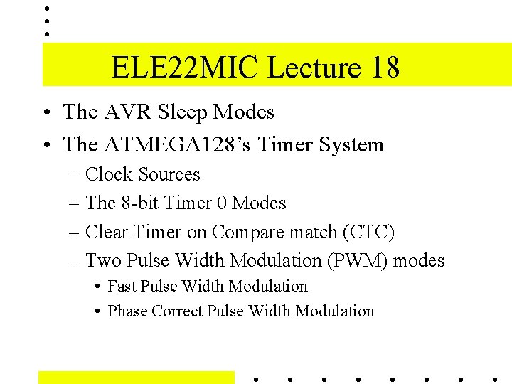
ELE 22 MIC Lecture 18 • The AVR Sleep Modes • The ATMEGA 128’s Timer System – Clock Sources – The 8 -bit Timer 0 Modes – Clear Timer on Compare match (CTC) – Two Pulse Width Modulation (PWM) modes • Fast Pulse Width Modulation • Phase Correct Pulse Width Modulation
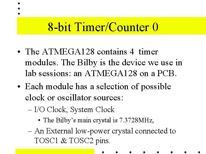
8 -bit Timer/Counter 0 • The ATMEGA 128 contains 4 timer modules. The Bilby is the device we use in lab sessions: an ATMEGA 128 on a PCB. • Each module has a selection of possible clock or oscillator sources: – I/O Clock, System Clock • The Bilby’s main crystal is 7. 3728 MHz, – An External low-power crystal connected to TOSC 1 & TOSC 2 pins.
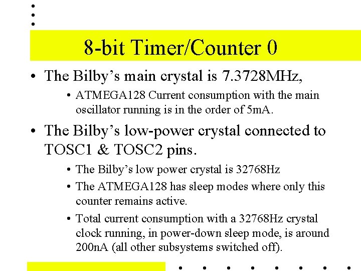
8 -bit Timer/Counter 0 • The Bilby’s main crystal is 7. 3728 MHz, • ATMEGA 128 Current consumption with the main oscillator running is in the order of 5 m. A. • The Bilby’s low-power crystal connected to TOSC 1 & TOSC 2 pins. • The Bilby’s low power crystal is 32768 Hz • The ATMEGA 128 has sleep modes where only this counter remains active. • Total current consumption with a 32768 Hz crystal clock running, in power-down sleep mode, is around 200 n. A (all other subsystems switched off).
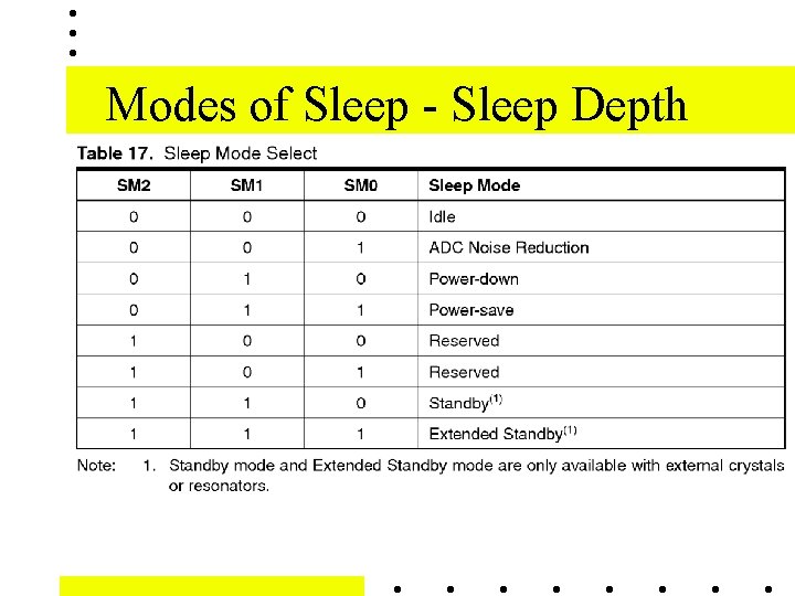
Modes of Sleep - Sleep Depth
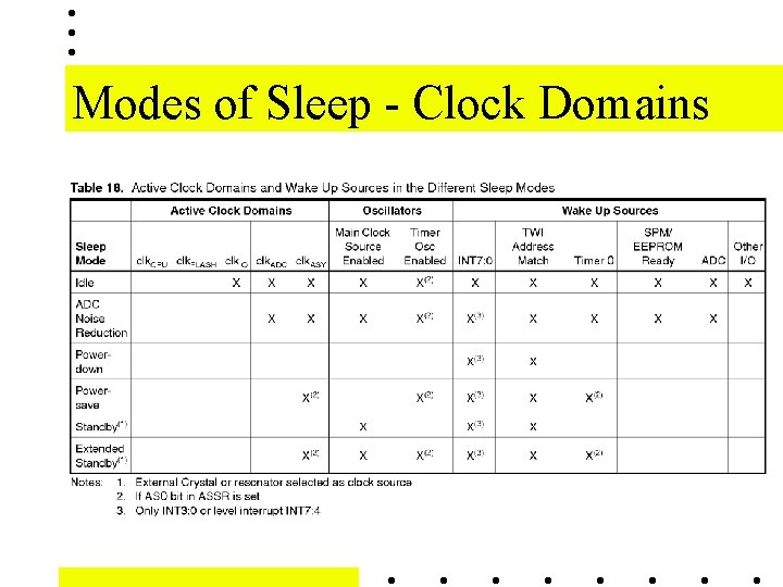
Modes of Sleep - Clock Domains
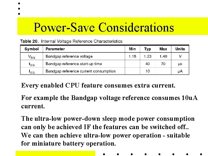
Power-Save Considerations Every enabled CPU feature consumes extra current. For example the Bandgap voltage reference consumes 10 u. A current. The ultra-low power-down sleep mode power consumption can only be achieved IF the features can be switched off. . We can then achieve ultra-low power operation - suitable for miniature battery operation.
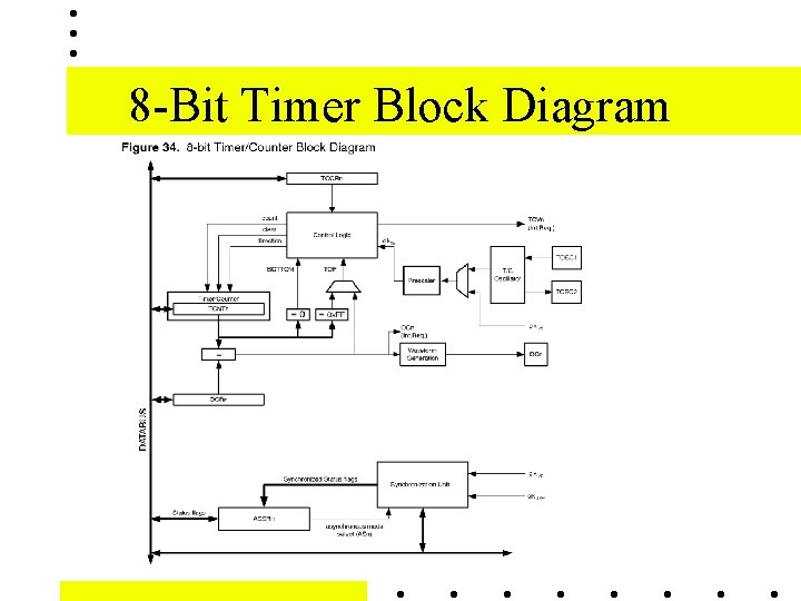
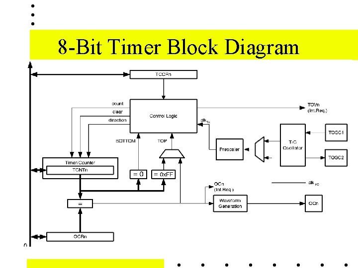
Timer / Counter 0 • Main Features: • Timer/Counter 0 is a general purpose, single channel, 8 -bit Timer/Counter module. The main features are: • Single Channel Counter • Clear Timer on Compare Match (Auto Reload)
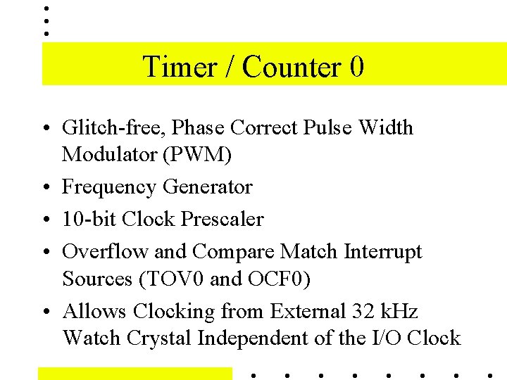
Timer / Counter 0 • Glitch-free, Phase Correct Pulse Width Modulator (PWM) • Frequency Generator • 10 -bit Clock Prescaler • Overflow and Compare Match Interrupt Sources (TOV 0 and OCF 0) • Allows Clocking from External 32 k. Hz Watch Crystal Independent of the I/O Clock
8 -Bit Timer Block Diagram
8 -Bit Timer Block Diagram
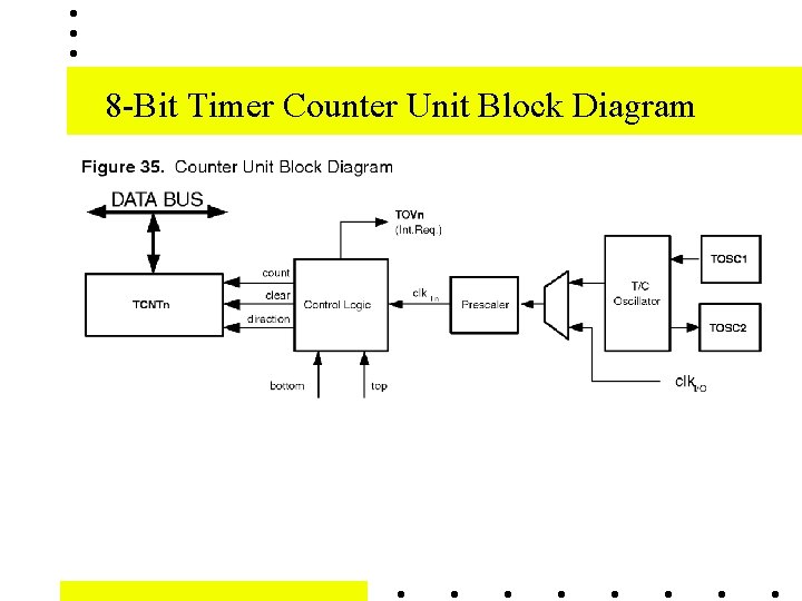
8 -Bit Timer Counter Unit Block Diagram
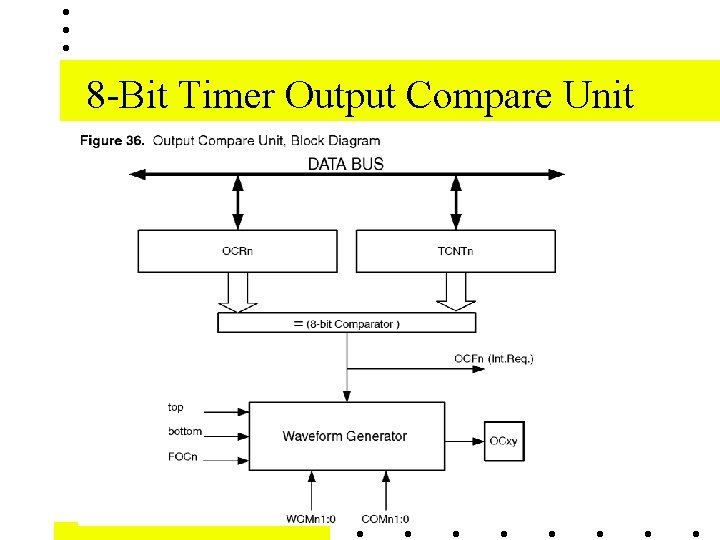
8 -Bit Timer Output Compare Unit
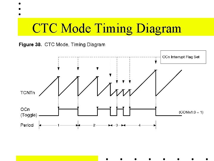
CTC Mode Timing Diagram
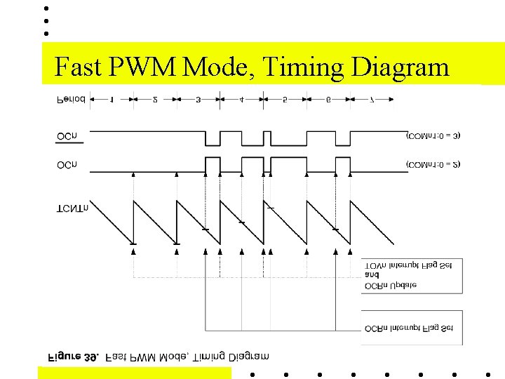
Fast PWM Mode, Timing Diagram
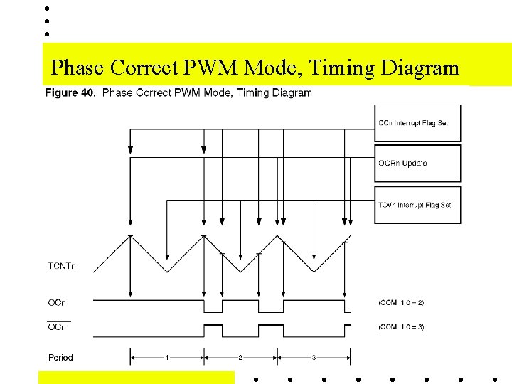
Phase Correct PWM Mode, Timing Diagram
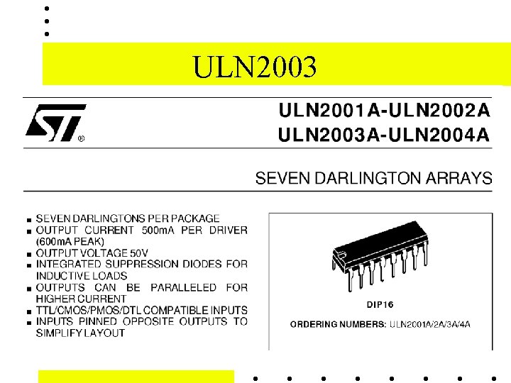
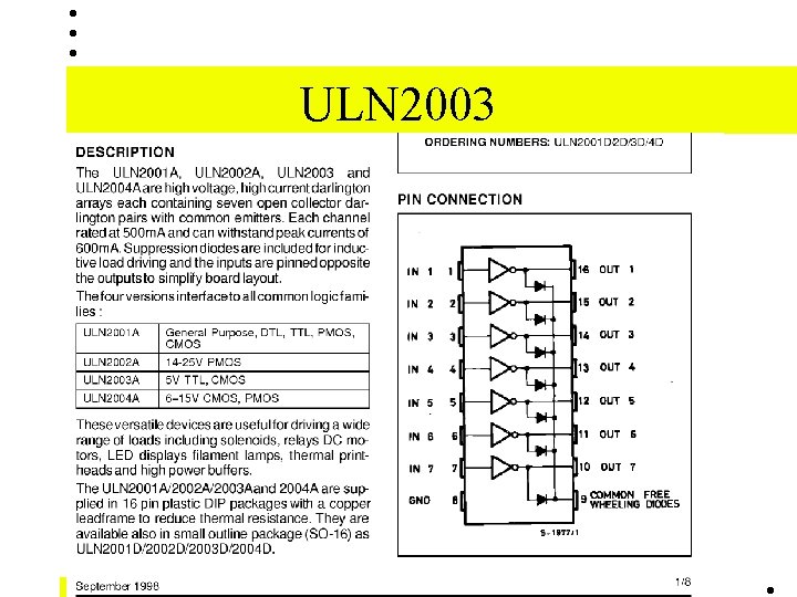
ULN 2003
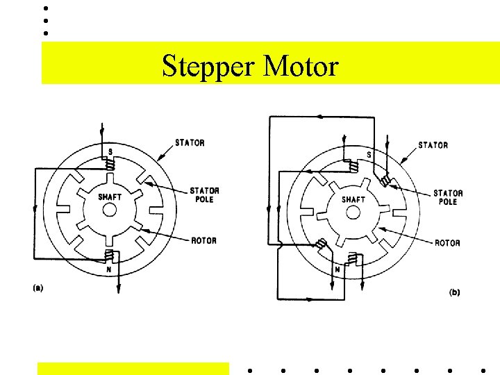
Stepper Motor
ULN 2003