ECE 5317 6351 Microwave Engineering Adapted from notes
- Slides: 25
ECE 5317 -6351 Microwave Engineering Adapted from notes by Prof. Jeffery T. Williams Fall 2018 Prof. David R. Jackson Dept. of ECE Notes 11 Waveguiding Structures Part 6: Planar Transmission Lines 1
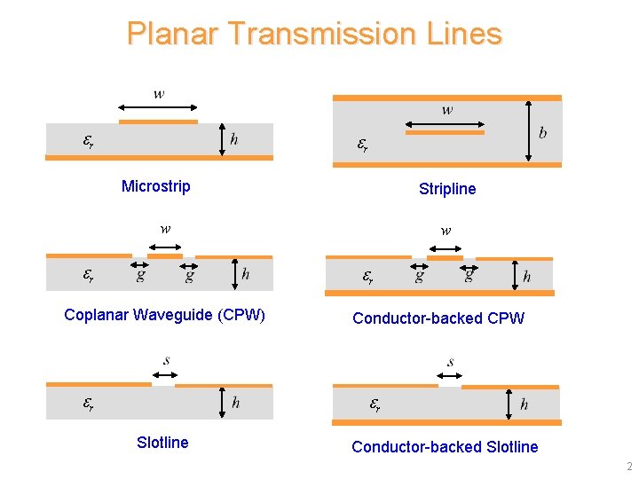
Planar Transmission Lines r r Microstrip Stripline w r Coplanar Waveguide (CPW) r Conductor-backed CPW r Slotline Conductor-backed Slotline 2
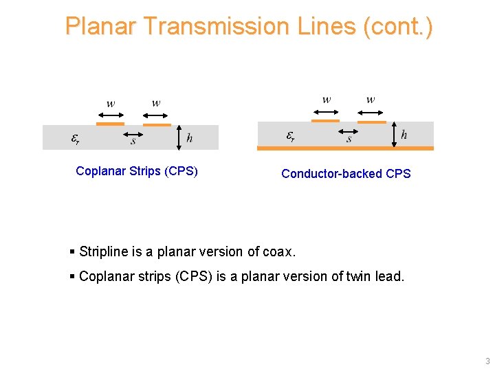
Planar Transmission Lines (cont. ) r Coplanar Strips (CPS) r Conductor-backed CPS § Stripline is a planar version of coax. § Coplanar strips (CPS) is a planar version of twin lead. 3
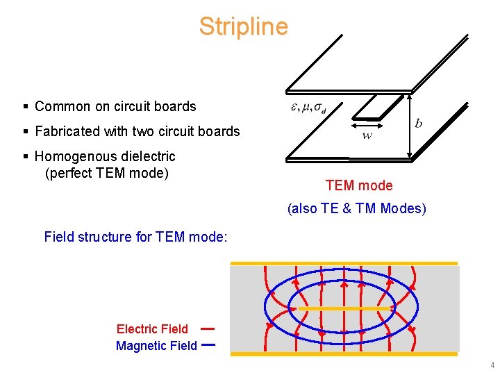
Stripline § Common on circuit boards § Fabricated with two circuit boards § Homogenous dielectric (perfect TEM mode) TEM mode (also TE & TM Modes) Field structure for TEM mode: Electric Field Magnetic Field 4
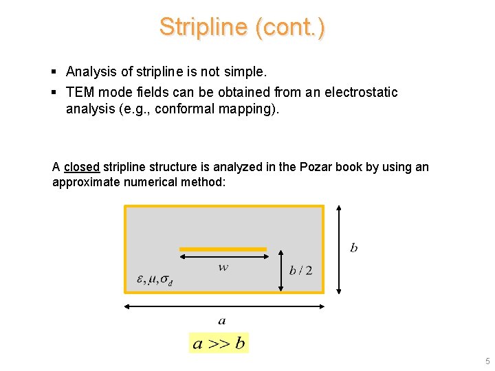
Stripline (cont. ) § Analysis of stripline is not simple. § TEM mode fields can be obtained from an electrostatic analysis (e. g. , conformal mapping). A closed stripline structure is analyzed in the Pozar book by using an approximate numerical method: 5
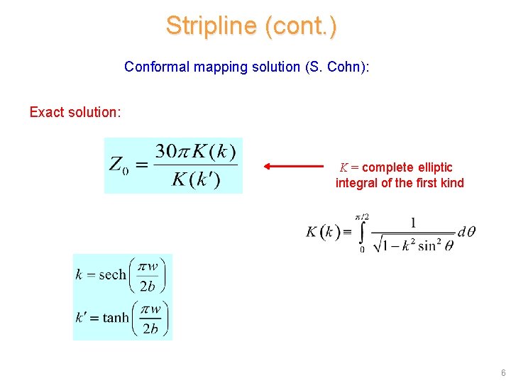
Stripline (cont. ) Conformal mapping solution (S. Cohn): Exact solution: K = complete elliptic integral of the first kind 6
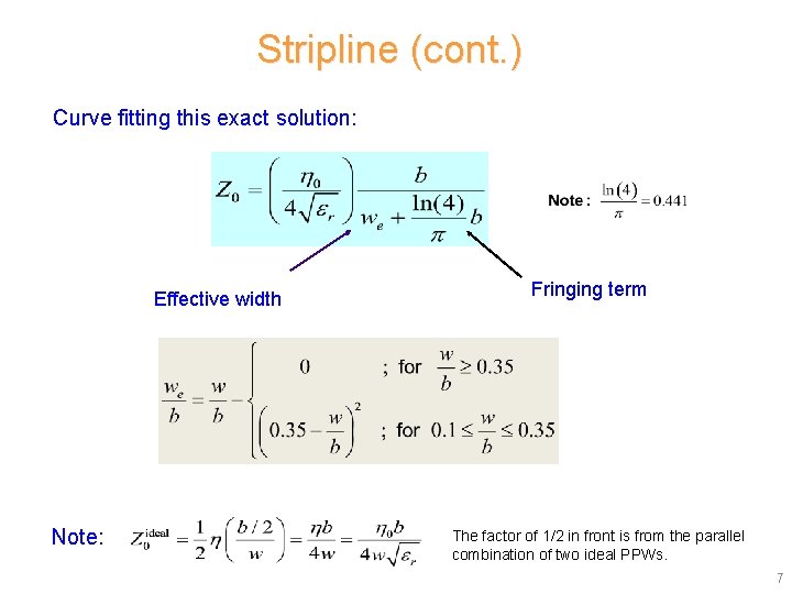
Stripline (cont. ) Curve fitting this exact solution: Effective width Note: Fringing term The factor of 1/2 in front is from the parallel combination of two ideal PPWs. 7
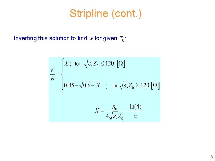
Stripline (cont. ) Inverting this solution to find w for given Z 0: 8
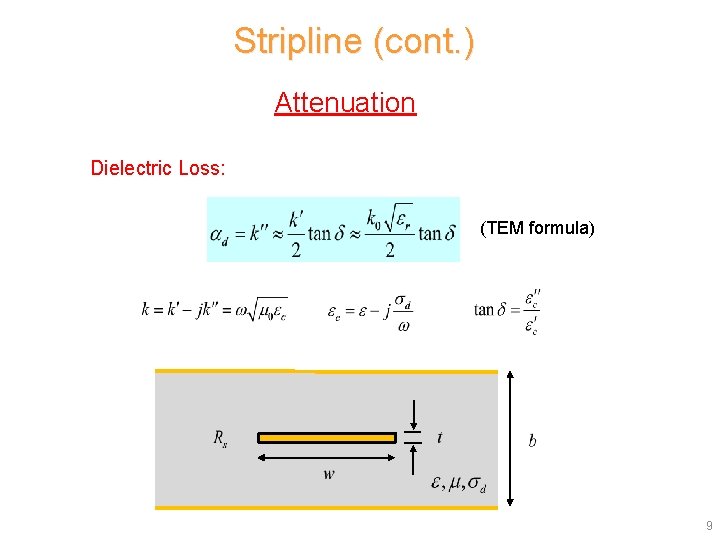
Stripline (cont. ) Attenuation Dielectric Loss: (TEM formula) 9
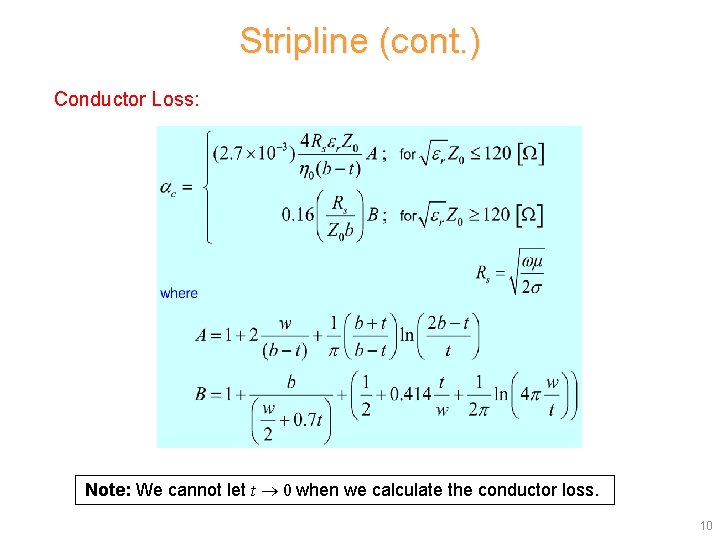
Stripline (cont. ) Conductor Loss: Note: We cannot let t 0 when we calculate the conductor loss. 10
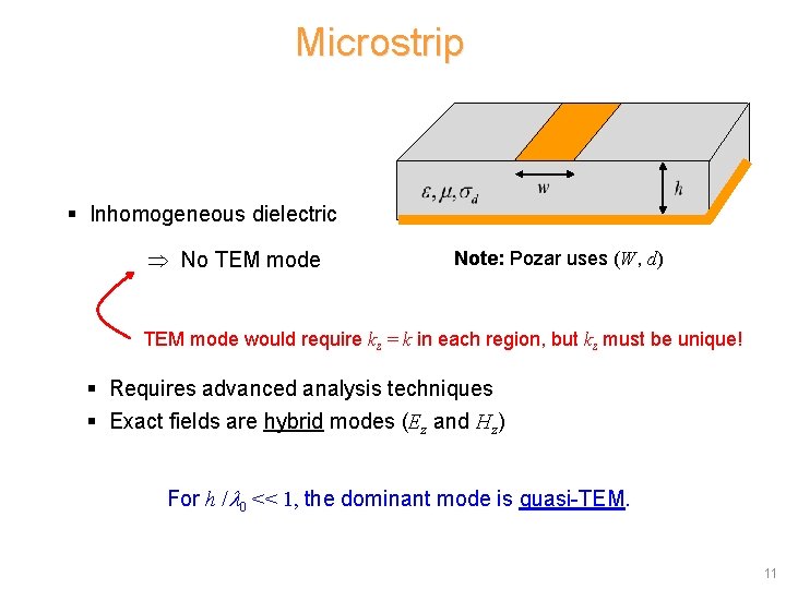
Microstrip § Inhomogeneous dielectric No TEM mode Note: Pozar uses (W, d) TEM mode would require kz = k in each region, but kz must be unique! § Requires advanced analysis techniques § Exact fields are hybrid modes (Ez and Hz) For h / 0 << 1, the dominant mode is quasi-TEM. 11
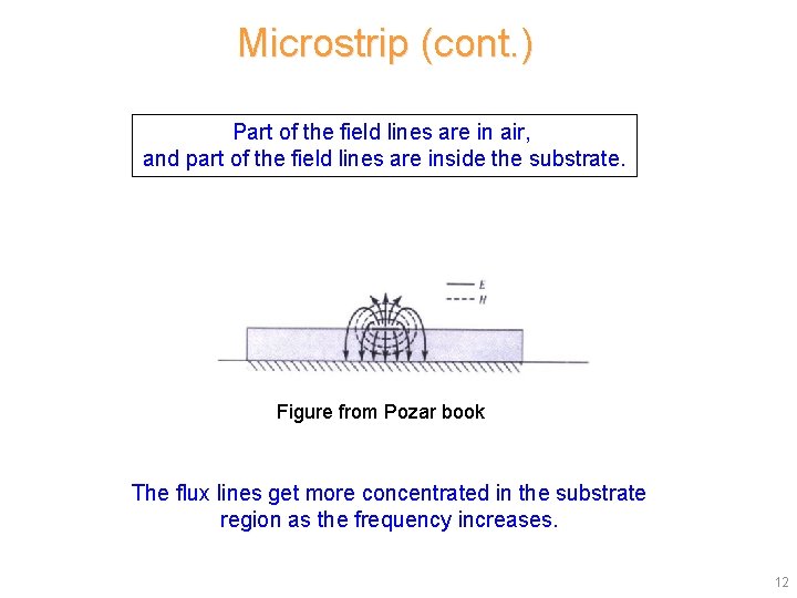
Microstrip (cont. ) Part of the field lines are in air, and part of the field lines are inside the substrate. Figure from Pozar book The flux lines get more concentrated in the substrate region as the frequency increases. 12
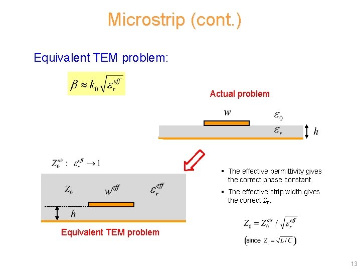
Microstrip (cont. ) Equivalent TEM problem: Actual problem § The effective permittivity gives the correct phase constant. § The effective strip width gives the correct Z 0. Equivalent TEM problem 13
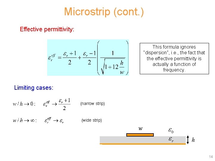
Microstrip (cont. ) Effective permittivity: This formula ignores “dispersion”, i. e. , the fact that the effective permittivity is actually a function of frequency. Limiting cases: (narrow strip) (wide strip) 14
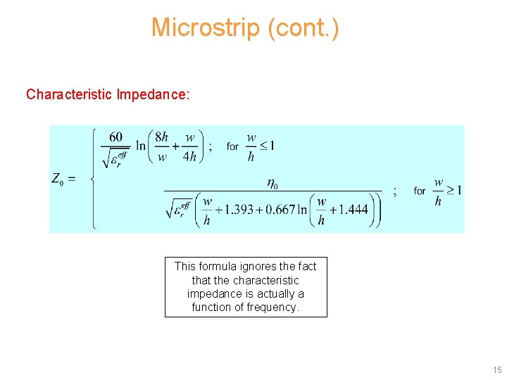
Microstrip (cont. ) Characteristic Impedance: This formula ignores the fact that the characteristic impedance is actually a function of frequency. 15
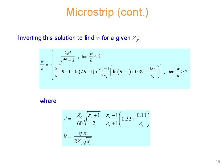
Microstrip (cont. ) Inverting this solution to find w for a given Z 0: where 16
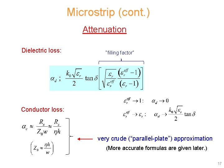
Microstrip (cont. ) Attenuation Dielectric loss: “filling factor” Conductor loss: very crude (“parallel-plate”) approximation (More accurate formulas are given later. ) 17
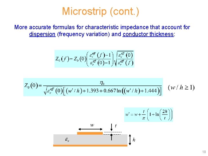
Microstrip (cont. ) More accurate formulas for characteristic impedance that account for dispersion (frequency variation) and conductor thickness: 18
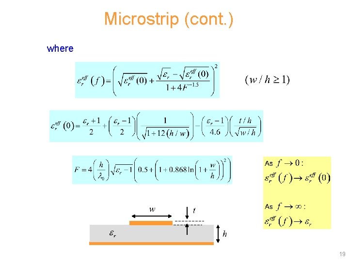
Microstrip (cont. ) where Note: 19
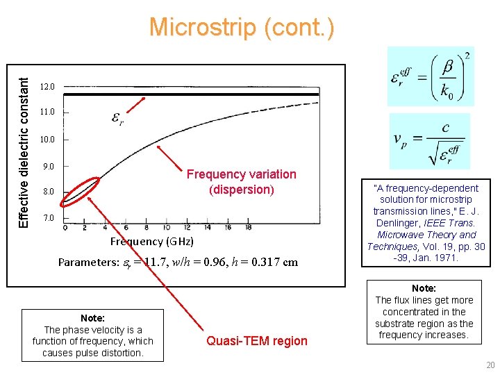
Effective dielectric constant Microstrip (cont. ) 12. 0 11. 0 10. 0 9. 0 Frequency variation (dispersion) 8. 0 7. 0 Frequency (GHz) Parameters: r = 11. 7, w/h = 0. 96, h = 0. 317 cm Note: The phase velocity is a function of frequency, which causes pulse distortion. Quasi-TEM region “A frequency-dependent solution for microstrip transmission lines, " E. J. Denlinger, IEEE Trans. Microwave Theory and Techniques, Vol. 19, pp. 30 -39, Jan. 1971. Note: The flux lines get more concentrated in the substrate region as the frequency increases. 20
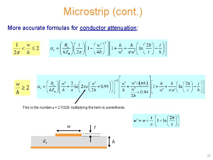
Microstrip (cont. ) More accurate formulas for conductor attenuation: This is the number e = 2. 71828 multiplying the term in parenthesis. 21
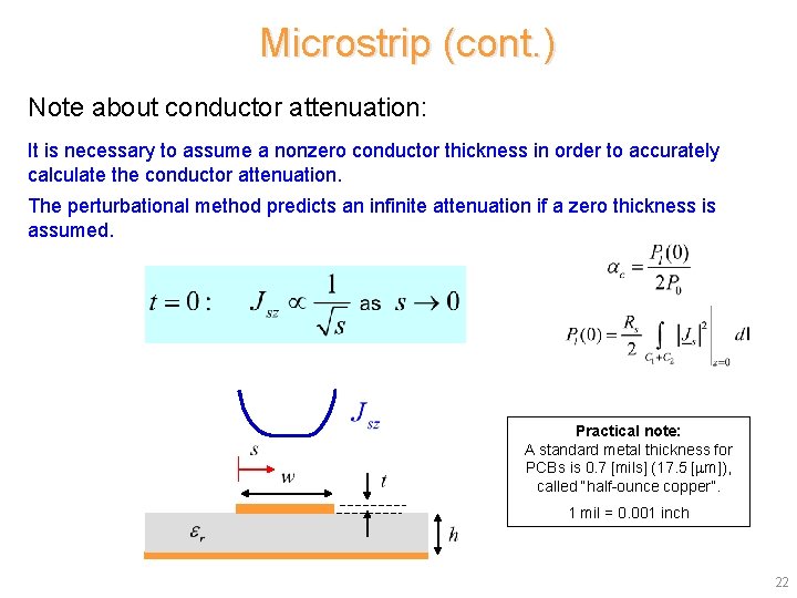
Microstrip (cont. ) Note about conductor attenuation: It is necessary to assume a nonzero conductor thickness in order to accurately calculate the conductor attenuation. The perturbational method predicts an infinite attenuation if a zero thickness is assumed. Practical note: A standard metal thickness for PCBs is 0. 7 [mils] (17. 5 [ m]), called “half-ounce copper”. 1 mil = 0. 001 inch 22
TXLINE This is a public-domain software for calculating the properties of some common planar transmission lines. http: //www. awrcorp. com/products/optional-products/tx-line-transmission-line-calculator 23
TXLINE (cont. ) TX-LINE: Transmission Line Calculator TX-LINE* software is a FREE and easy-to-use Windows-based interactive transmission line calculator for the analysis and synthesis of transmission line structures. Register and Download Your FREE Copy of TX-LINE Software Today! TX-LINE software enables users to enter either physical or electrical characteristics for common transmission mediums: Microstrip Stripline Coplanar waveguide (WG) Grounded coplanar WG Slotline Learn more: TX-LINE Software Video Demonstration (3 minutes) *Note: TX-LINE software is embedded within NI AWR Design Environment and can be launched from the "Tools" menu. 24
Microstrip (cont. ) REFERENCES L. G. Maloratsky, Passive RF and Microwave Integrated Circuits, Elsevier, 2004. I. Bahl and P. Bhartia, Microwave Solid State Circuit Design, Wiley, 2003. R. A. Pucel, D. J. Masse, and C. P. Hartwig, “Losses in Microstrip, ” IEEE Trans. Microwave Theory and Techniques, pp. 342 -350, June 1968. R. A. Pucel, D. J. Masse, and C. P. Hartwig, “Corrections to ‘Losses in Microstrip’, ” IEEE Trans. Microwave Theory and Techniques, Dec. 1968, p. 1064. 25