ECE 445 Spring 2019 Head Orientation Tracking Module


 ● Regulators ○ The regulators")


- Slides: 23
ECE 445 Spring 2019 - Head Orientation Tracking Module for Headphones Group 46 Molly Fane, Sally Zhou, Cary Zhu
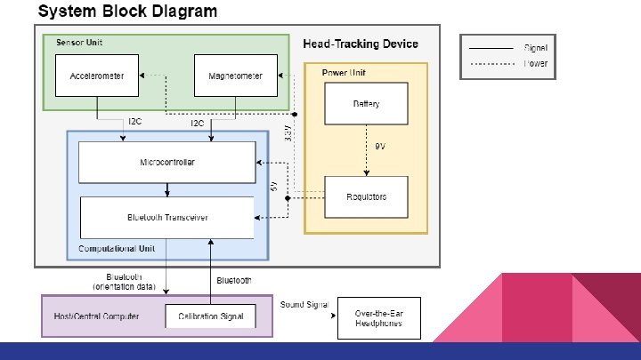
Introduction ● Worked with Professor Eli Fieldsteel, Director of Experimental Music Studios ● Deliver a more immersive and realistic audio experience ○ Make it feel as though the sound is coming from fixed positions in a room despite moving your head
Objective ● A device capable of ○ Attaching to any pair of over-the-ear headphones ○ Communicating accurate data about the orientation of the head back to computer ● Orientation: roll, pitch, yaw
Physical Diagram
PCB Indicator LED’s Sensor Chip & Peripherals Bluetooth Connections Bluetooth Module Battery Connector Jack 3. 3 v Regulator 5 v Regulator ATMega 2560 Chip Test Points for Code Upload
PCB Design: Extra Features ● EAGLE used to design PCB ● Schottky Diodes on USB and 9 V power supplies. ● Test points ● Power LED ● Status LED ● USB and Bluetooth breakout boards.
Power Unit ● Battery: 9 V Battery (5% Tolerance) ● Regulators ○ The regulators take 9 volts from battery to produce 5± 0. 5 V and 3. 3± 0. 3 V ○ Capable of delivering 0. 501 A for 3. 3 V ○ Capable of delivering 0. 50 m. A for 5 V
Power Unit Schematic
Computational Unit: Microcontroller ● Drives accelerometer, magnetometer to produce orientation ● Used ATmega 2560 Chip ● Drives Bluetooth controller ● Programmed using USB breakout board
Computational Unit: Bluetooth Transceiver ● Sustains connection with computer for a minimum 5 meters away ● Returns data at 9600 Baud (50 Hz framerate for 3 float-64 values) ● Accessed through serial connection within Super. Collider or through a Pu. TTY Terminal
Sensor Unit ● Accelerometer ○ Records 3 -axis acceleration data ● Magnetometer ○ Records 3 -axis magnetic north data ● Used LSM 303 ● Communicate ≥ 30 Hz (fastest 5. 376 k. Hz)
Sensor Unit - Tilt Compensated Heading ● Accelerometer outputs gravity vector: (G 1, G 2, G 3) ● Magnetometer outputs Magnetic North vector: (N 1, N 2, N 3) ● Trigonometry
Sensor Unit - Magnetometer Calibration
Software: Algorithm ● Calibration Weights and Offsets ● Low-pass filter ○ 2 tap weighted average ● Tilt Compensated Heading Calculation ● Bluetooth communication ○ On/Off with LED status ○ Reset front direction
Software: Front Calibration ● Yaw is calibrated using the current “front” orientation Updated_Yaw = mod(Sensed_Yaw - Front_Yaw, 2π) ● Subtract yaw from instance front reset trigger is pressed from all later yaw calculations ● Modulo 360°
Software: Super. Collider Integration ● Platform for audio synthesis and algorithmic composition
Challenges ● PCB Assembly ○ Sensor chip ○ Small capacitors ○ Lack of test points
Challenges ● PCB Assembly ○ Sensor chip ○ Small capacitors ○ Lack of test points
Challenges ● Code often would not upload to ATMega 2560 ● Irregular behavior ● Did not diagnose problem before damaging original board
Future Development ● Improved PCB design for better portability and integration ● Have a complete sound system to produce a variety of types of sounds ● Possible projects with VR applications
Acknowledgements ● ● Professor Eli Fieldsteel Zhen Qin Professor Arne Fliflet ECE 445 Course Staff
Thank You Questions?