EAT 353 STRUCTURAL ANALYSIS II ANALYSIS OF STATICALLY






- Slides: 65
EAT 353 STRUCTURAL ANALYSIS II ANALYSIS OF STATICALLY INDETERMINATE STRUCTURE BY THE FORCE METHOD ILYA BINTI JOOHARI
COURSE OUTCOME CO 1 Ability to analyse the statically andindeterminate trussesbeam, applying force of flexibility method
Topics 1. Statically Indeterminate Structures 2. Force Method Of Analysis: General Procedure 3. Maxwell’s Theorem Of Reciprocal Displacements; Betti’s Law 4. Force Method Of Analysis: Beams 5. Force Method Of Analysis: Frames 6. Force Method Of Analysis: Trusses 7. Composite Structures 8. Additional Remarks On The Force Method Of Analysis 9. Symmetric Structures 10. Influence Lines For Statically Indeterminate Beams 11. Qualitative Influence Lines For Frames
1. Statically Indeterminate Structure
Statically Indeterminate Structure Advantages and Disadvantages o For a given loading, the maximum stress and deflection of an indeterminate structure are generally small than those of its statically determinate counterpart. o Statically indeterminate structure has a tendency to redistribute its load to its redundant supports in cases of faulty design of overloading.
Statically Indeterminate Structure Advantages and Disadvantages o Although statically indeterminate structure can support loading with thinner members and with increased stability compared to their statically determinate counterpart, the cost savings in material must be compared with the added cost to fabricate the structures since often it becomes more costly to construct the supports and joints of an indeterminate structure. o Careful of differential displacement of the supports as well.
2. Force Method Of Analysis: General Procedure
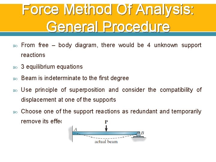
Force Method Of Analysis: General Procedure From free – body diagram, there would be 4 unknown support reactions 3 equilibrium equations Beam is indeterminate to the first degree Use principle of superposition and consider the compatibility of displacement at one of the supports Choose one of the support reactions as redundant and temporarily remove its effect on the beam
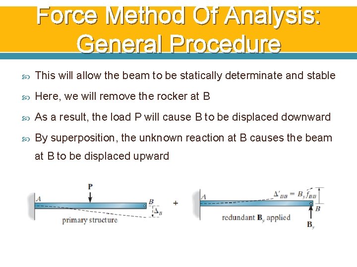
Force Method Of Analysis: General Procedure This will allow the beam to be statically determinate and stable Here, we will remove the rocker at B As a result, the load P will cause B to be displaced downward By superposition, the unknown reaction at B causes the beam at B to be displaced upward
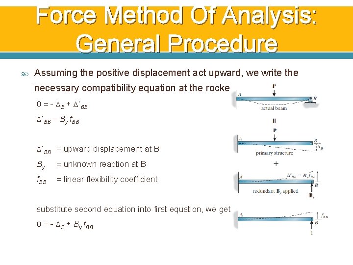
Force Method Of Analysis: General Procedure Assuming the positive displacement act upward, we write the necessary compatibility equation at the rocker as: 0 = - ∆B + ∆’BB = By f. BB ∆’BB = upward displacement at B By = unknown reaction at B f. BB = linear flexibility coefficient substitute second equation into first equation, we get: 0 = - ∆B + By f. BB
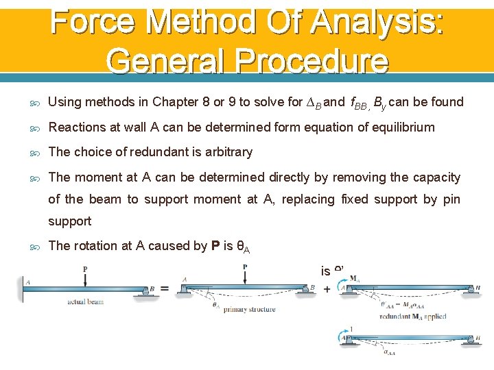
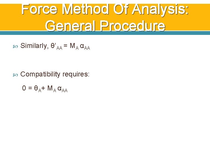
Force Method Of Analysis: General Procedure Using methods in Chapter 8 or 9 to solve for ∆B and f. BB , By can be found Reactions at wall A can be determined form equation of equilibrium The choice of redundant is arbitrary The moment at A can be determined directly by removing the capacity of the beam to support moment at A, replacing fixed support by pin support The rotation at A caused by P is θA The rotation at A caused by redundant MA at A is θ’AA
Force Method Of Analysis: General Procedure Similarly, θ’AA = MA αAA Compatibility requires: 0 = θA+ MA αAA
3. Maxwell’s Theorem of Reciprocal Displacements; Betti’s Law
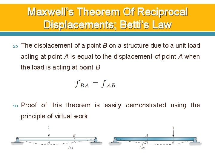
Maxwell’s Theorem Of Reciprocal Displacements; Betti’s Law The displacement of a point B on a structure due to a unit load acting at point A is equal to the displacement of point A when the load is acting at point B Proof of this theorem is easily demonstrated using the principle of virtual work
Maxwell’s Theorem Of Reciprocal Displacements; Betti’s Law The theorem also applies for reciprocal rotations The rotation at a point B on a structure due to a unit couple moment at point A is equal to the rotation at point A when the unit couple is acting at point B
4. Force Method Of Analysis: Beams
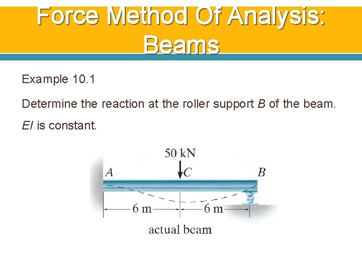
Force Method Of Analysis: Beams Example 10. 1 Determine the reaction at the roller support B of the beam. EI is constant.
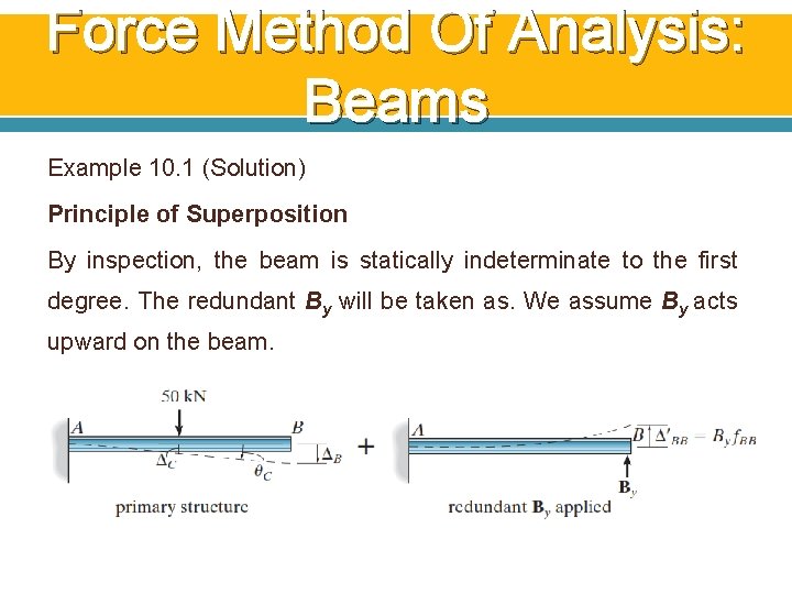
Force Method Of Analysis: Beams Example 10. 1 (Solution) Principle of Superposition By inspection, the beam is statically indeterminate to the first degree. The redundant By will be taken as. We assume By acts upward on the beam.
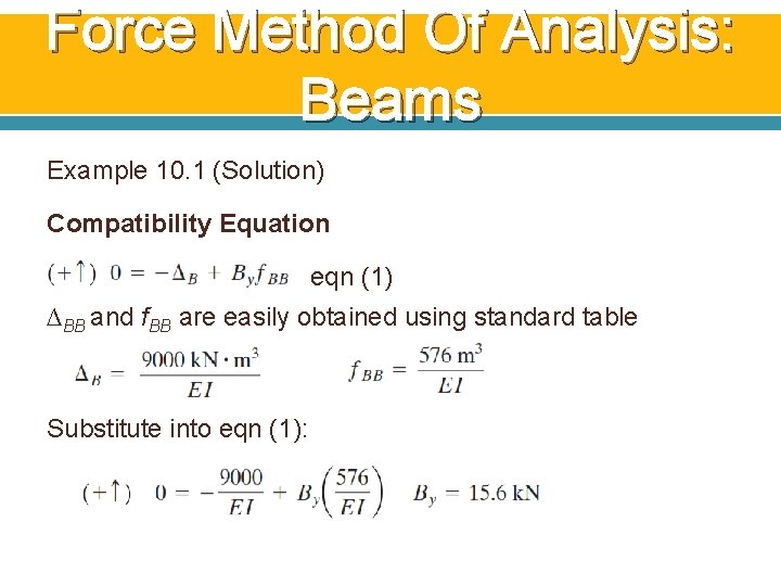
Force Method Of Analysis: Beams Example 10. 1 (Solution) Compatibility Equation eqn (1) ∆BB and f. BB are easily obtained using standard table Substitute into eqn (1):
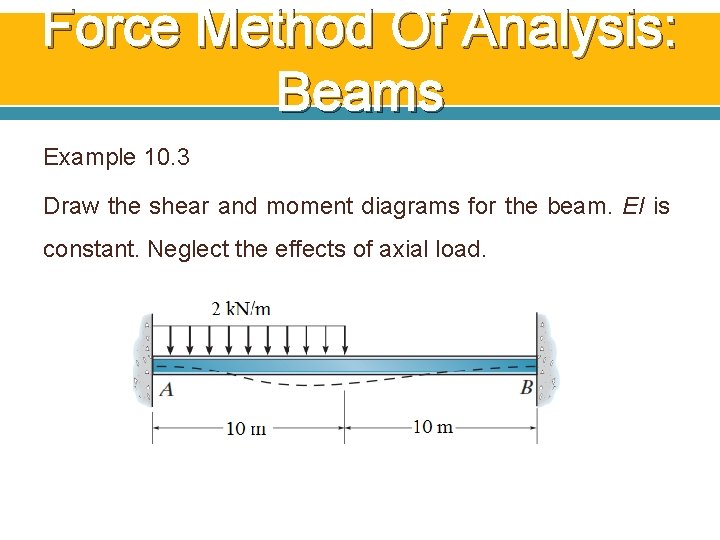
Force Method Of Analysis: Beams Example 10. 3 Draw the shear and moment diagrams for the beam. EI is constant. Neglect the effects of axial load.
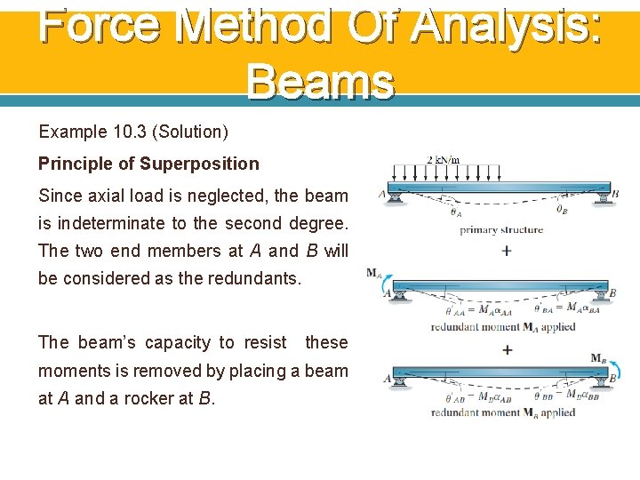
Force Method Of Analysis: Beams Example 10. 3 (Solution) Principle of Superposition Since axial load is neglected, the beam is indeterminate to the second degree. The two end members at A and B will be considered as the redundants. The beam’s capacity to resist these moments is removed by placing a beam at A and a rocker at B.
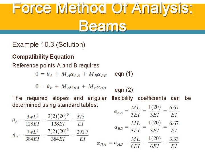
Force Method Of Analysis: Beams Example 10. 3 (Solution) Compatibility Equation Reference points A and B requires eqn (1) eqn (2) The required slopes and angular flexibility coefficients can be determined using standard tables.
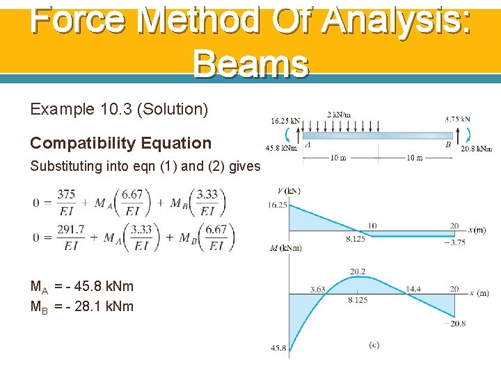
Force Method Of Analysis: Beams Example 10. 3 (Solution) Compatibility Equation Substituting into eqn (1) and (2) gives: MA = - 45. 8 k. Nm MB = - 28. 1 k. Nm
5. Force Method Of Analysis: Frames
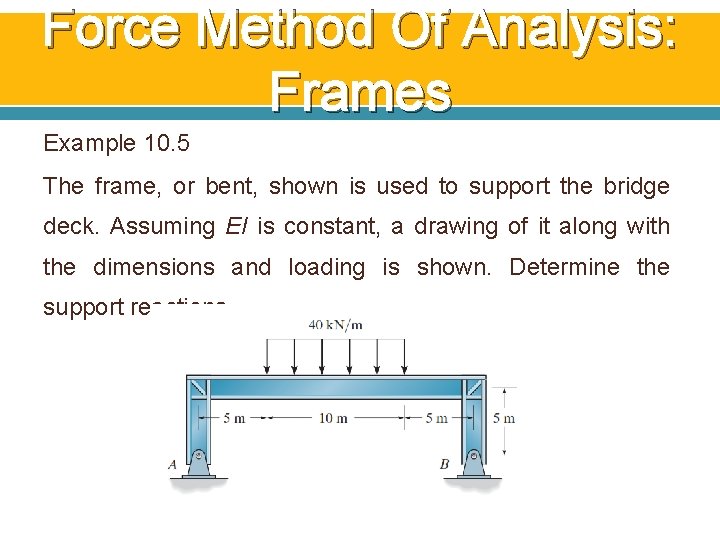
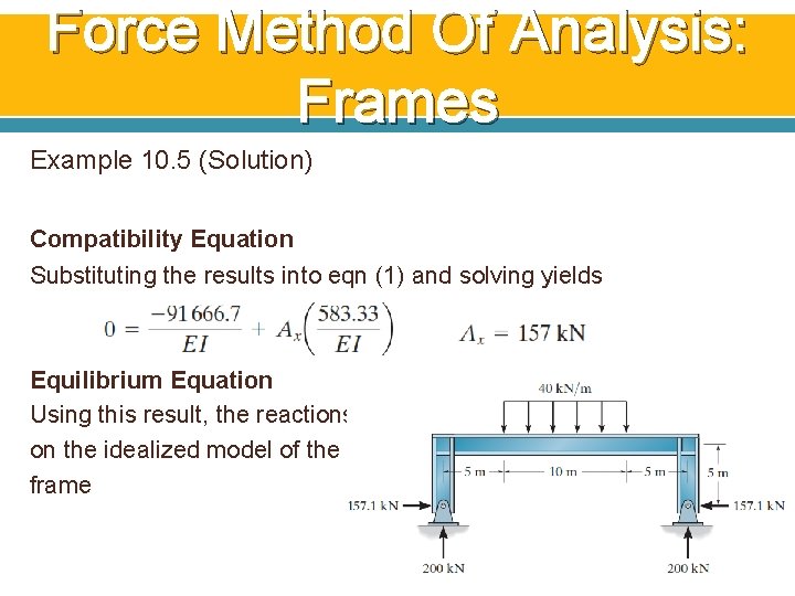
Force Method Of Analysis: Frames Example 10. 5 The frame, or bent, shown is used to support the bridge deck. Assuming EI is constant, a drawing of it along with the dimensions and loading is shown. Determine the support reactions.
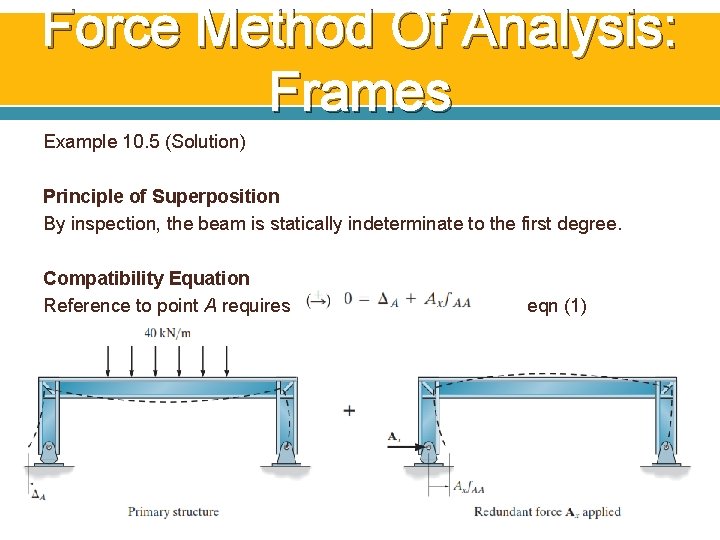
Force Method Of Analysis: Frames Example 10. 5 (Solution) Principle of Superposition By inspection, the beam is statically indeterminate to the first degree. Compatibility Equation Reference to point A requires eqn (1)
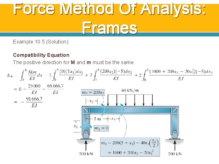
Force Method Of Analysis: Frames Example 10. 5 (Solution) Compatibility Equation The positive direction for M and m must be the same.
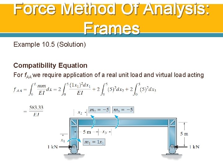
Force Method Of Analysis: Frames Example 10. 5 (Solution) Compatibility Equation For f. AA we require application of a real unit load and virtual load acting at A.
Force Method Of Analysis: Frames Example 10. 5 (Solution) Compatibility Equation Substituting the results into eqn (1) and solving yields Equilibrium Equation Using this result, the reactions on the idealized model of the frame
6. Force Method of Analysis: Trusses
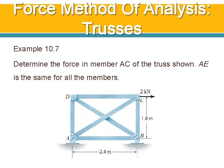
Force Method Of Analysis: Trusses Example 10. 7 Determine the force in member AC of the truss shown. AE is the same for all the members.
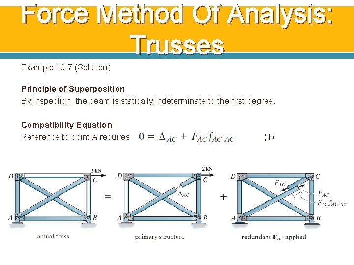
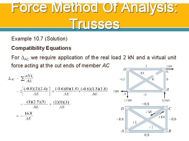
Force Method Of Analysis: Trusses Example 10. 7 (Solution) Principle of Superposition By inspection, the beam is statically indeterminate to the first degree. Compatibility Equation Reference to point A requires (1)
Force Method Of Analysis: Trusses Example 10. 7 (Solution) Compatibility Equations For ∆AC we require application of the real load 2 k. N and a virtual unit force acting at the cut ends of member AC
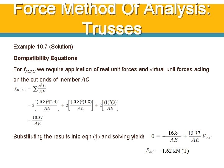
Force Method Of Analysis: Trusses Example 10. 7 (Solution) Compatibility Equations For f. ACAC we require application of real unit forces and virtual unit forces acting on the cut ends of member AC Substituting the results into eqn (1) and solving yields
7. Composite Structures
Composite Structures Composite structures are composed of some members subjected only to axial force, while other members are subjected to bending. If the structure is statically indeterminate, the force method can conveniently be used for its analysis.
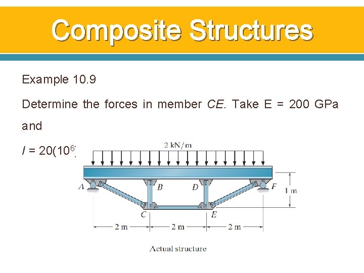
Composite Structures Example 10. 9 Determine the forces in member CE. Take E = 200 GPa and I = 20(106) mm 4
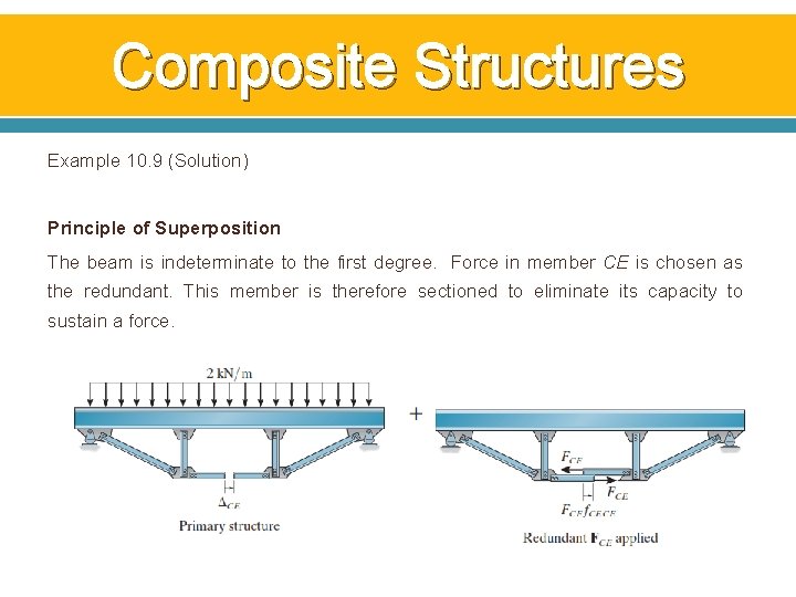
Composite Structures Example 10. 9 (Solution) Principle of Superposition The beam is indeterminate to the first degree. Force in member CE is chosen as the redundant. This member is therefore sectioned to eliminate its capacity to sustain a force.
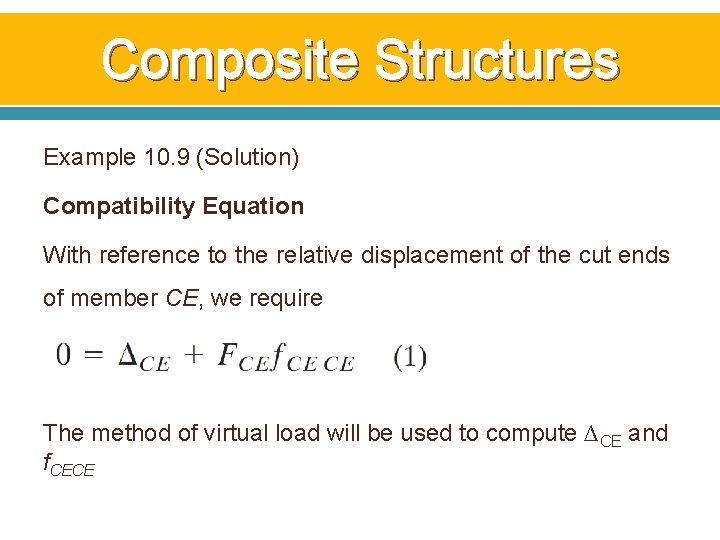
Composite Structures Example 10. 9 (Solution) Compatibility Equation With reference to the relative displacement of the cut ends of member CE, we require The method of virtual load will be used to compute ∆CE and f. CECE
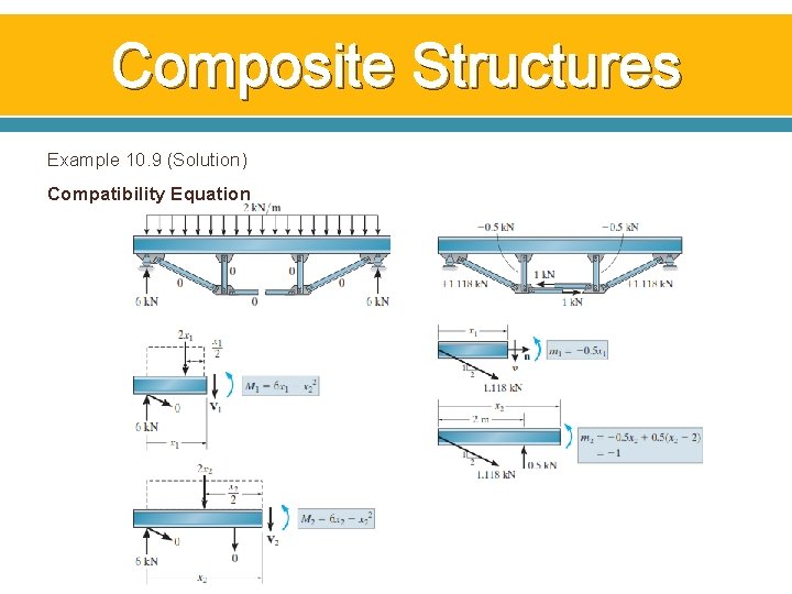
Composite Structures Example 10. 9 (Solution) Compatibility Equation
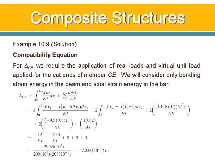
Composite Structures Example 10. 9 (Solution) Compatibility Equation For ∆CE we require the application of real loads and virtual unit load applied for the cut ends of member CE. We will consider only bending strain energy in the beam and axial strain energy in the bar.
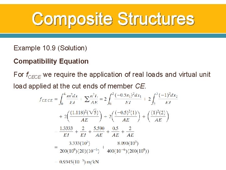
Composite Structures Example 10. 9 (Solution) Compatibility Equation For f. CECE we require the application of real loads and virtual unit load applied at the cut ends of member CE.
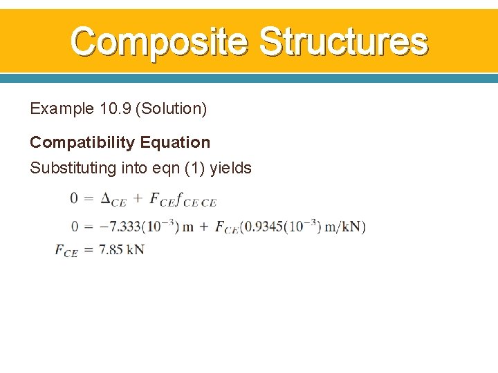
Composite Structures Example 10. 9 (Solution) Compatibility Equation Substituting into eqn (1) yields
8. Additional Remarks on the Force Method of Analysis
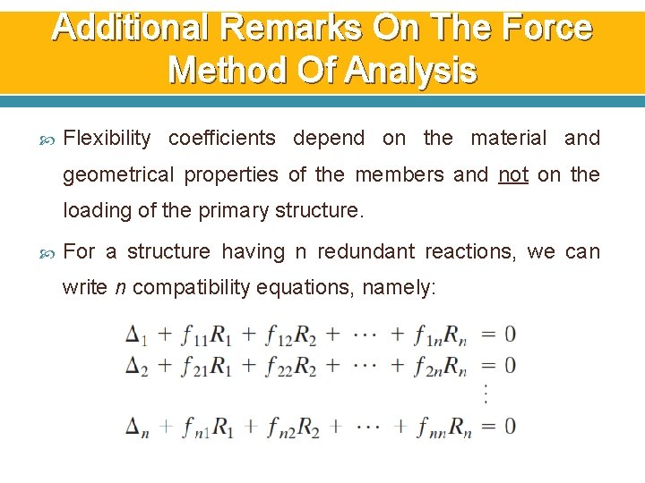
Additional Remarks On The Force Method Of Analysis Flexibility coefficients depend on the material and geometrical properties of the members and not on the loading of the primary structure. For a structure having n redundant reactions, we can write n compatibility equations, namely:
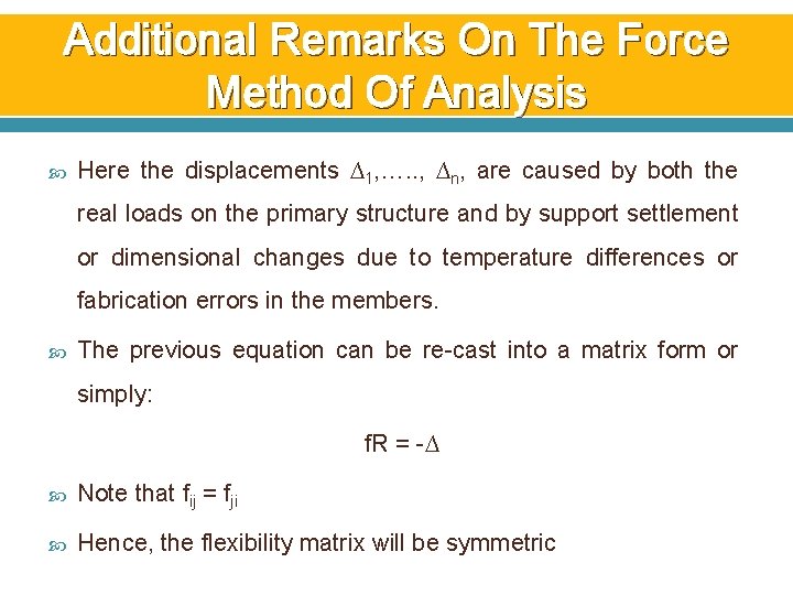
Additional Remarks On The Force Method Of Analysis Here the displacements ∆1, …. . , ∆n, are caused by both the real loads on the primary structure and by support settlement or dimensional changes due to temperature differences or fabrication errors in the members. The previous equation can be re-cast into a matrix form or simply: f. R = -∆ Note that fij = fji Hence, the flexibility matrix will be symmetric
9. Symmetric Structures
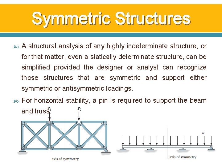
Symmetric Structures A structural analysis of any highly indeterminate structure, or for that matter, even a statically determinate structure, can be simplified provided the designer or analyst can recognize those structures that are symmetric and support either symmetric or antisymmetric loadings. For horizontal stability, a pin is required to support the beam and truss.
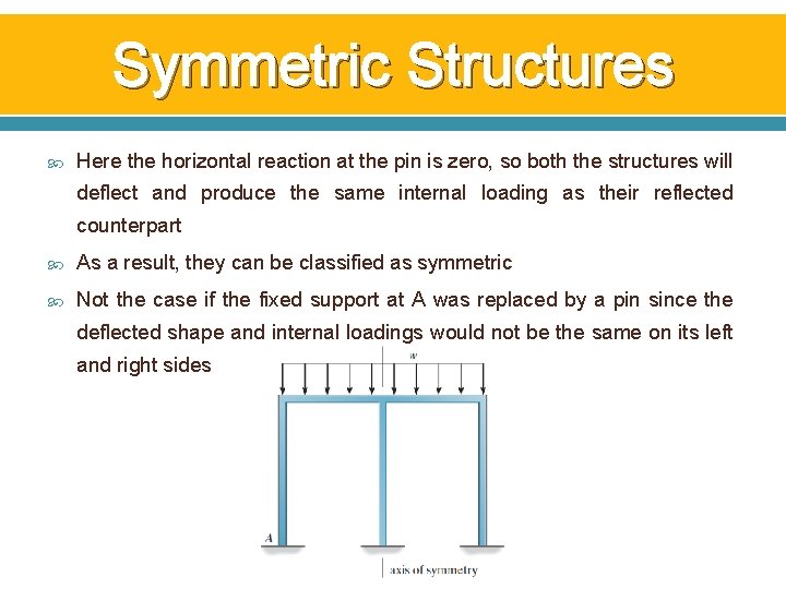
Symmetric Structures Here the horizontal reaction at the pin is zero, so both the structures will deflect and produce the same internal loading as their reflected counterpart As a result, they can be classified as symmetric Not the case if the fixed support at A was replaced by a pin since the deflected shape and internal loadings would not be the same on its left and right sides
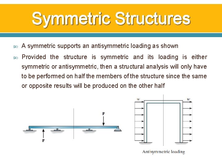
Symmetric Structures A symmetric supports an antisymmetric loading as shown Provided the structure is symmetric and its loading is either symmetric or antisymmetric, then a structural analysis will only have to be performed on half the members of the structure since the same or opposite results will be produced on the other half
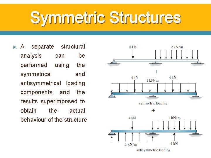
Symmetric Structures A separate structural analysis can be performed using the symmetrical and antisymmetrical loading components and the results superimposed to obtain the actual behaviour of the structure
10. Influence Lines For Statically Indeterminate Beams
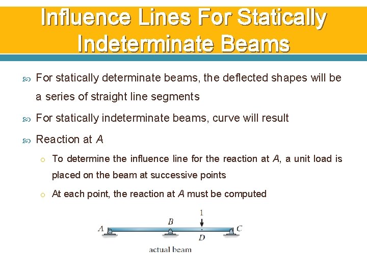
Influence Lines For Statically Indeterminate Beams For statically determinate beams, the deflected shapes will be a series of straight line segments For statically indeterminate beams, curve will result Reaction at A o To determine the influence line for the reaction at A, a unit load is placed on the beam at successive points o At each point, the reaction at A must be computed
Influence Lines For Statically Indeterminate Beams Reaction at A o A plot of these results yields the influence line o The reaction at A can be determined by the force method o The principle of superposition is applied
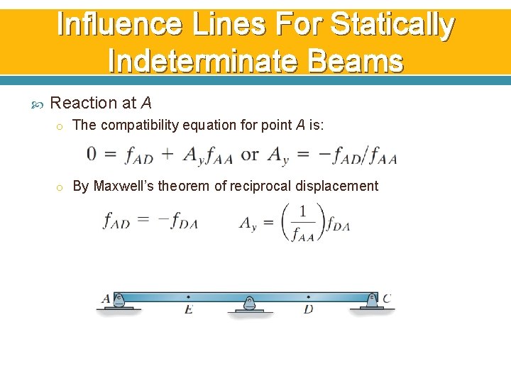
Influence Lines For Statically Indeterminate Beams Reaction at A o The compatibility equation for point A is: o By Maxwell’s theorem of reciprocal displacement
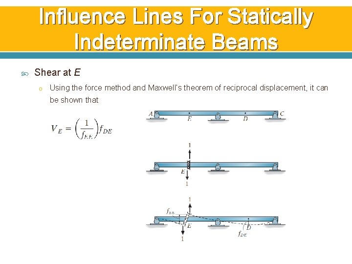
Influence Lines For Statically Indeterminate Beams Shear at E o Using the force method and Maxwell’s theorem of reciprocal displacement, it can be shown that
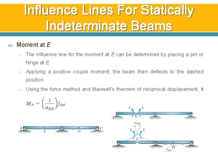
Influence Lines For Statically Indeterminate Beams Moment at E o The influence line for the moment at E can be determined by placing a pin or hinge at E o Applying a positive couple moment, the beam then deflects to the dashed position o Using the force method and Maxwell’s theorem of reciprocal displacement, it can be shown that
11. Qualitative Influence Line for Frames
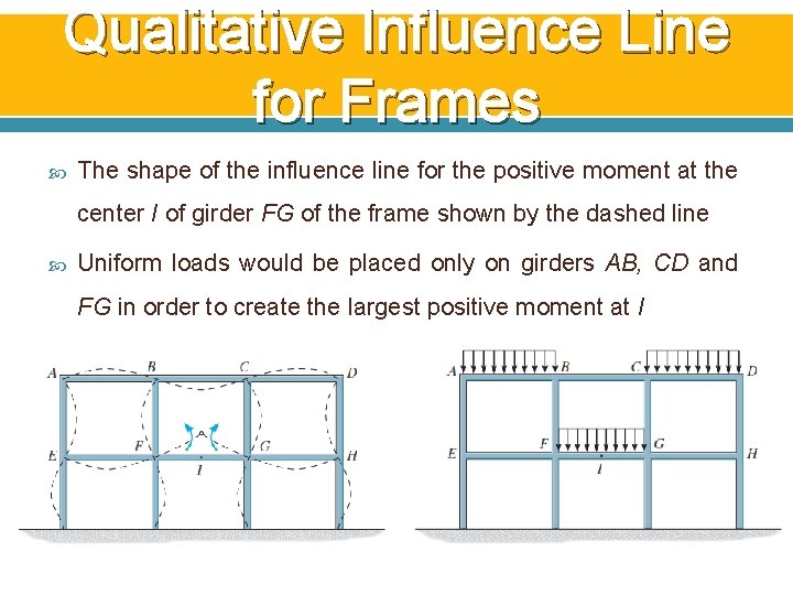
Qualitative Influence Line for Frames The shape of the influence line for the positive moment at the center I of girder FG of the frame shown by the dashed line Uniform loads would be placed only on girders AB, CD and FG in order to create the largest positive moment at I
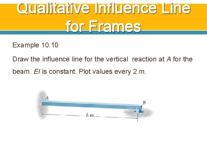
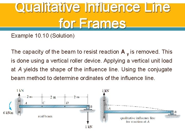
Qualitative Influence Line for Frames Example 10. 10 Draw the influence line for the vertical reaction at A for the beam. EI is constant. Plot values every 2 m.
Qualitative Influence Line for Frames Example 10. 10 (Solution) The capacity of the beam to resist reaction A y is removed. This is done using a vertical roller device. Applying a vertical unit load at A yields the shape of the influence line. Using the conjugate beam method to determine ordinates of the influence line.
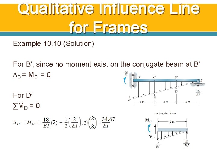
Qualitative Influence Line for Frames Example 10. 10 (Solution) For B’, since no moment exist on the conjugate beam at B’ ∆B = MB’ = 0 For D’ ∑MD = 0
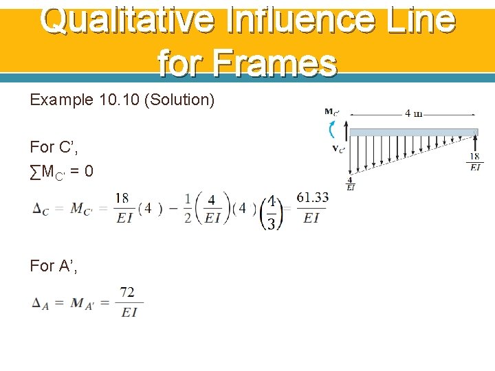
Qualitative Influence Line for Frames Example 10. 10 (Solution) For C’, ∑MC’ = 0 For A’,
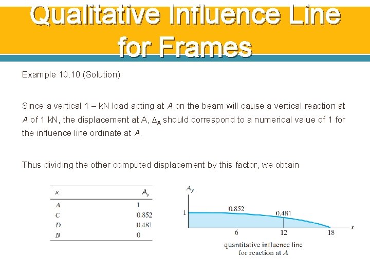
Qualitative Influence Line for Frames Example 10. 10 (Solution) Since a vertical 1 – k. N load acting at A on the beam will cause a vertical reaction at A of 1 k. N, the displacement at A, ∆A should correspond to a numerical value of 1 for the influence line ordinate at A. Thus dividing the other computed displacement by this factor, we obtain
END