DirectCurrentCircuits Electromotive Force Resistors in Series and in


- Slides: 20

Direct�Current�Circuits • Electromotive Force • Resistors in Series and in Parallel • Kirchhoff ’s Rules • RC Circuits • Electrical Instruments • Household Wiring and Electrical Safety

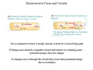
Electromotive Force • A device that produces an electric field and thu s may cause charges to move around a circuit • Example: a battery or generator • In Fig 1, the potential difference of resistor is equal to emf of the battery • However real battery has always internal resistance r (Fig 2), thus the terminal voltage reduces to • Note that � emf is equivalent to the opencircuit voltage • What is the voltage in the battery’s label ? ?

Electromotive Force (2) • There are voltage drop through r and R • The voltage equation of the circuit is • The flowing current is • The power balance in the circuit

Matching the Load

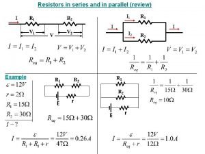
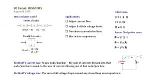
Resistor in Serial • Resistors connected in serial have the same flowing current I = I 1 = I 2 = I 3 V = V 1 + V 2 + V 3 V I R t = I 1 R 1 + I 2 R 2 + I 3 R 3 Rt = R 1 + R 2 + R 3 5

Resistor in Parallel • Resistors in parallel have the same voltage’s magnitude § V = V 1 = V 2 = V 3 § It = I 1 + I 2 + I 3 § V/Rt = V/R 1 + V/R 2 + V/R 3 V § 1/Rt = 1/R 1 + 1/R 2 + 1/R 3 6

Calculate Equivalent R

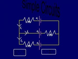
KIRCHHOFF’S RULES • In analyzing complex circuit (more than single loop), we need kirchhoff’s rules. • The principles are: 1. The sum of the currents entering any junction in a circuit must equal the sum of the currents leaving that junction: 2. The sum of the potential differences across all elements around any closed circuit loop must be zero:

First Rules

Second Rules

Example Substitute equation (1) into (2) Equation (3) devide by 2 : Find I 1, I 2, I 3 ? Solution Khirchoff 1 Khirchoff 2 : voltage in loop circuit 11

RC CIRCUITS • A circuit containing a series combination of a resistor and a ca -pacitor is called an RC circuit. • Normally, we analyzes the system during steady-state. • Now, we will analyze the circuit prior to steady-state i. e. transient state

Charging Capacitor • The capacitor is initially uncharged • There is no current while switch S is open (Fig. b) • If the switch is closed at t= 0 (Fig. c) the charge begins to flow, setting up a current in the circ uit, and the capacitor begins to charge • Note that during charging, charges do not jump across the capacitor plates because the gap between the plates represents an open circuit • The charge is transferred between each plate and its connecting wire due to E by the battery • As the plates become charged, the potential difference across the capacitor increases • Once the maximum charged is reached, the current in the circuit is zero

Charging Capacitor (2) • Apply Kirchhoff’s loop rule to the circuit after the switch is closed • Note that q and I are instantaneous values that depend on time • At the instant the switch is closed (t = 0) the charge on the capacitor is zero. The initial current • At this time, the potential difference from the battery terminals appears entirely across the resistor • When the charge of capacitor is maximum Q, The charge stop flowing and the current stop flowing as well. The V battery appears entirely across the capacitor

Charging Capacitor (3) • The current is equation , substitute to voltage • Integrating this expression • we can write this expression as

Charging Capacitor (4) • The current is • The quantity RC is called the time constant • It represents the time it takes the current to d ecrease to 1/e of its initial value • In time , while in time

Discharging a Capacitor • The circuit consists of a capacitor with initial charge Q, a resistor, and a switch • When the switch is open (Fig. a), the potential difference Q /C exists across the capacitor • There is zero potential difference across the resistor • If the switch is closed at t = 0 (Fig. b) the capacitor begins to discharge through the resistor • As a result, the current will flow and the charge in the capacitor will be reduced

Discharging a Capacitor (2) • The equation for the circuit is • Substitute into this expression • Integrating this expression • The current is

ELECTRICAL INSTRUMENTS • The Ammeter Ideally, an ammeter should have zero resistance , Why? • Voltmeter An ideal voltmeter has infinite resistance, Why?

HOUSEHOLD WIRING AND ELECTRICAL SAFETY • Utility distributes the power via a pair of wires (live and neutral wire) • Each house is connected in parallel to this line • A meter is connected in series with the live wire entering the house to record the household’s usage of electricity • After the meter, the wire splits so that there are several separate circuits in parallel distributed throughout the house • Each circuit contains a circuit breaker • The wire and circuit breaker for each circuit are carefully selected to meet the current demands
 Electromotive force and circuits
 Current resistance and electromotive force
 Electromotive force unit
 Electromotive force unit
 Electromotive force unit
 Gaya gerak listrik adalah
 Sources of electromotive force
 Electromotive force ppt
 Electromotive force
 The mass of a rectangular sheet of wood varies jointly
 Resistors in series and parallel
 Resistors in series and parallel equations
 Simplifying resistors
 Identical resistance
 A package contains 12 resistors 3 of which are defective
 Ceramic composition resistors
 Walmart resistors
 Two cylindrical resistors are made from the same material
 Series aiding and series opposing
 Maclaurin series vs taylor series
 Heisenberg 1925 paper
