Digital Design Lectures 11 12 Shift Registers and


- Slides: 19
Digital Design Lectures 11 & 12 Shift Registers and Counters
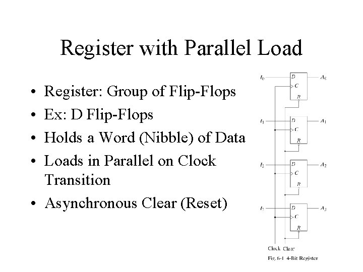
Register with Parallel Load • • Register: Group of Flip-Flops Ex: D Flip-Flops Holds a Word (Nibble) of Data Loads in Parallel on Clock Transition • Asynchronous Clear (Reset)
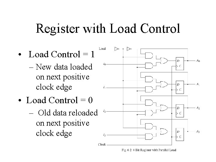
Register with Load Control • Load Control = 1 – New data loaded on next positive clock edge • Load Control = 0 – Old data reloaded on next positive clock edge
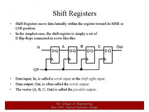
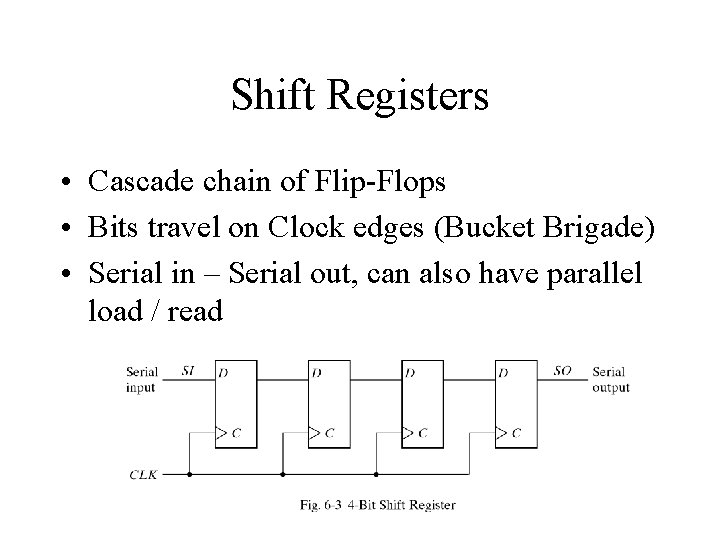
Shift Registers • Cascade chain of Flip-Flops • Bits travel on Clock edges (Bucket Brigade) • Serial in – Serial out, can also have parallel load / read
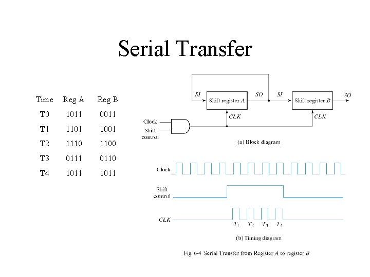
Serial Transfer Time Reg A Reg B T 0 1011 0011 T 1 1101 1001 T 2 1110 1100 T 3 0111 0110 T 4 1011
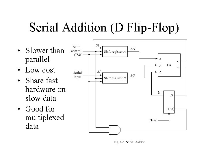
Serial Addition (D Flip-Flop) • Slower than parallel • Low cost • Share fast hardware on slow data • Good for multiplexed data
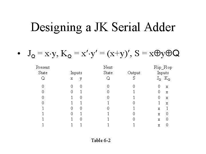
Designing a JK Serial Adder • JQ = x y, KQ = x y = (x+y) , S = x y Q Present State Q 0 0 1 1 Inputs x y 0 0 1 1 0 1 0 1 Next State Q Output S 0 0 0 1 1 1 0 1 0 0 1 Table 6 -2 Flip_Flop Inputs JQ KQ 0 0 0 1 x x x x 1 0 0 0
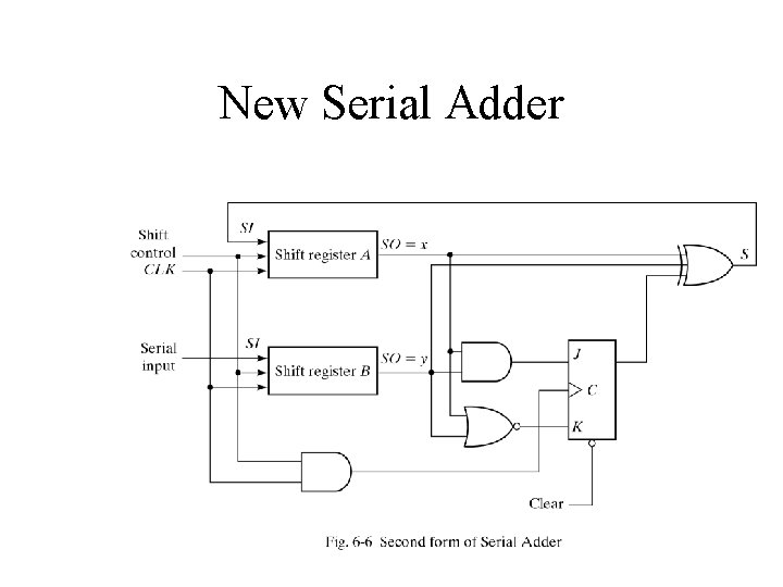
New Serial Adder
Universal Shift Register • Clear • Clock • Shift – Right – Left • Load • Read • Control S 1 0 0 1 1
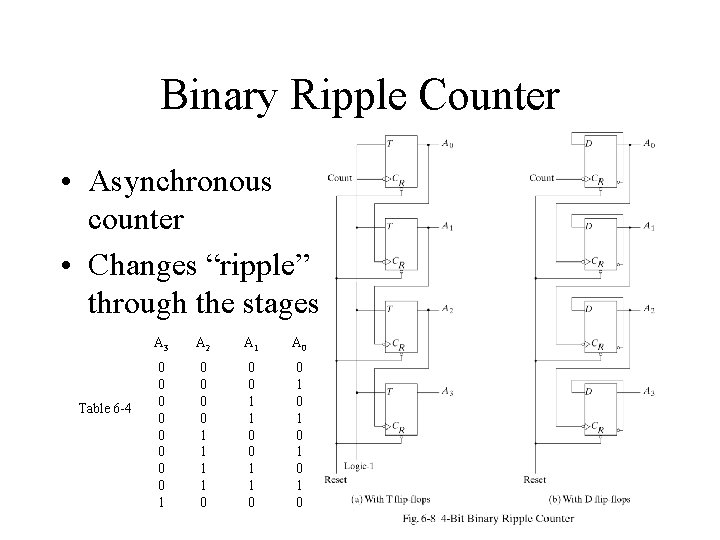
Binary Ripple Counter • Asynchronous counter • Changes “ripple” through the stages Table 6 -4 A 3 A 2 A 1 A 0 0 0 0 0 1 1 0 0 0 1 1 0 0 1 0 1 0
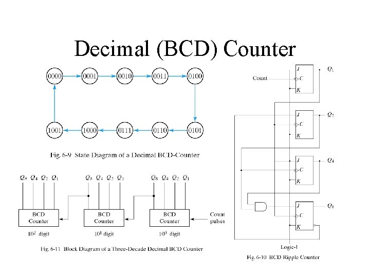
Decimal (BCD) Counter
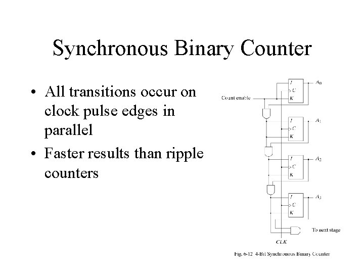
Synchronous Binary Counter • All transitions occur on clock pulse edges in parallel • Faster results than ripple counters
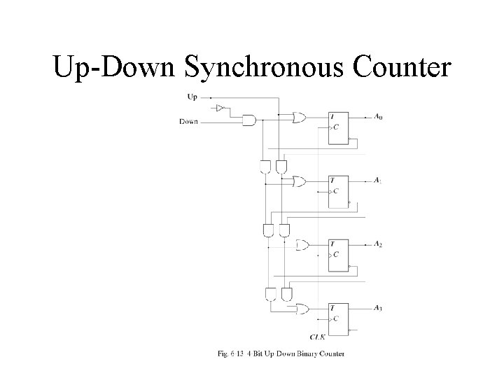
Up-Down Synchronous Counter
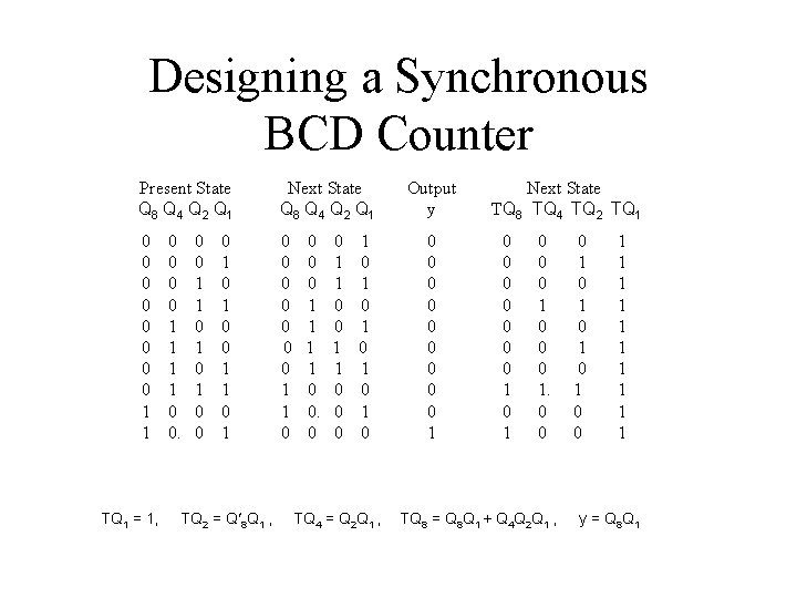
Designing a Synchronous BCD Counter Present State Q 8 Q 4 Q 2 Q 1 Next State Q 8 Q 4 Q 2 Q 1 0 0 0 0 1 1 0 TQ 1 = 1, 0 0 1 1 0 1 0 0 1 1 0 1 TQ 2 = Q 8 Q 1 , 0 0 0 1 1 0 0 0 1 0 0 TQ 4 = Q 2 Q 1 , Output y 0 0 0 0 0 1 Next State TQ 8 TQ 4 TQ 2 TQ 1 0 0 0 0 1. 0 0 TQ 8 = Q 8 Q 1 + Q 4 Q 2 Q 1 , 0 1 0 1 0 0 1 1 1 1 1 y = Q 8 Q 1
4 -bit Synchronous Counter with Parallel Load Clear Clk Load Count Function 0 1 1 1 x x 1 0 0 x x 1 0 Clear Load Count No Change Table 6 -6
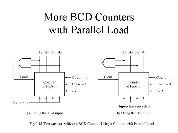
More BCD Counters with Parallel Load
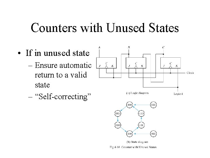
Counters with Unused States • If in unused state – Ensure automatic return to a valid state – “Self-correcting”
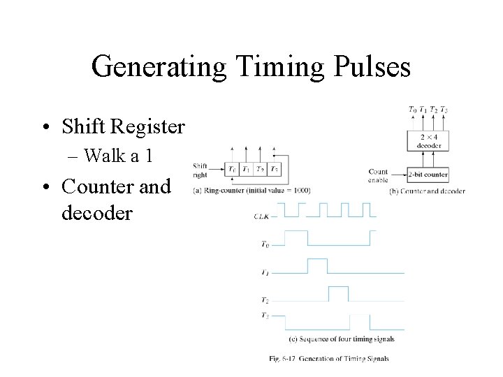
Generating Timing Pulses • Shift Register – Walk a 1 • Counter and decoder
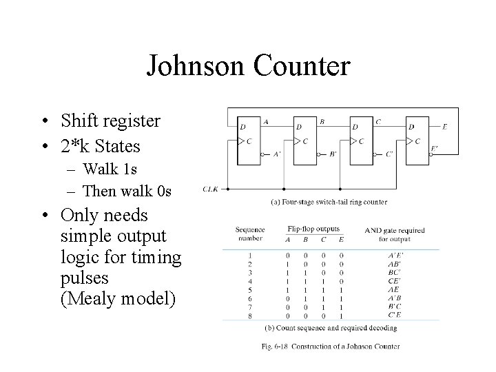
Johnson Counter • Shift register • 2*k States – Walk 1 s – Then walk 0 s • Only needs simple output logic for timing pulses (Mealy model)