CSE 475 Satellite and Space Networks MER KORAK

- Slides: 42
CSE 475 Satellite and Space Networks ÖMER KORÇAK omer. korcak@marmara. edu. tr Marmara University Department of Computer Engineering Satellite Networks Research Laboratory (SATLAB) Department of Computer Engineering, Boğaziçi University Istanbul, Turkey
OUTLINE • Satellites – GEO, MEO, LEO • • • High Altitude Platforms Integration Scenario Problem Definition & Solution Approach 2
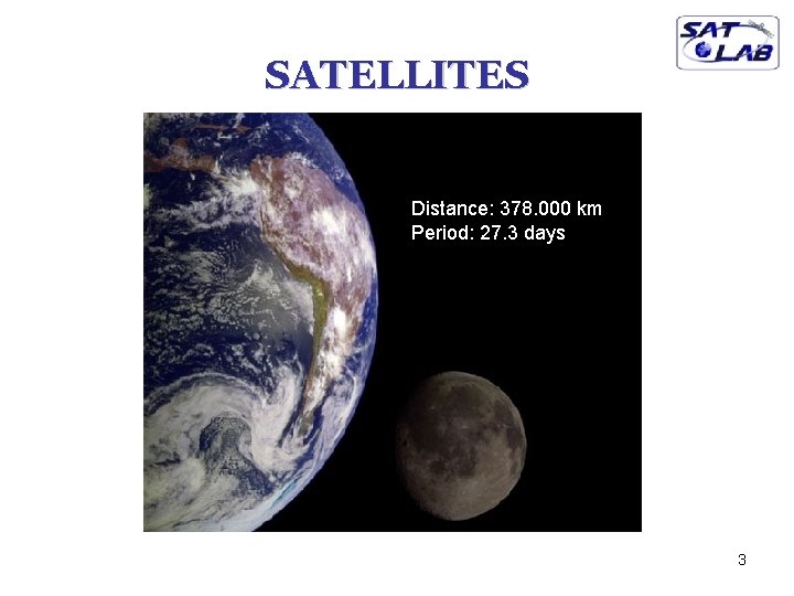
SATELLITES Distance: 378. 000 km Period: 27. 3 days 3
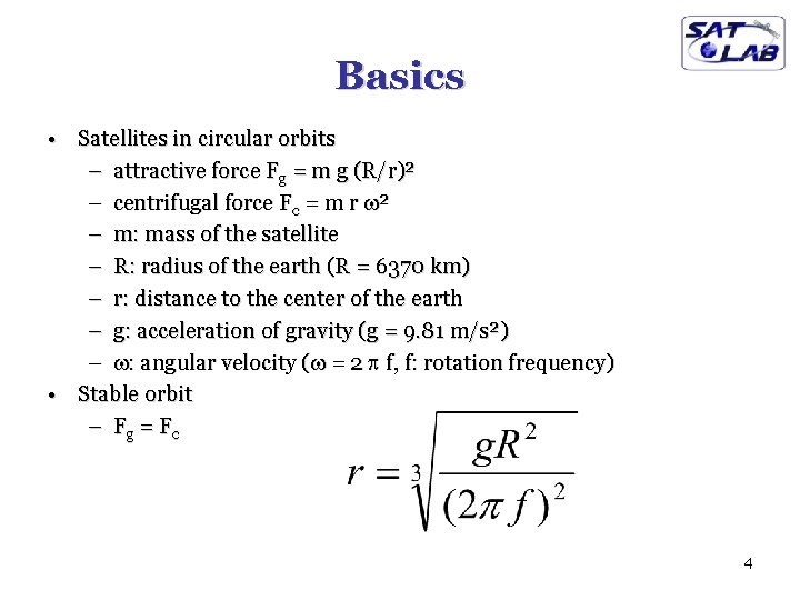
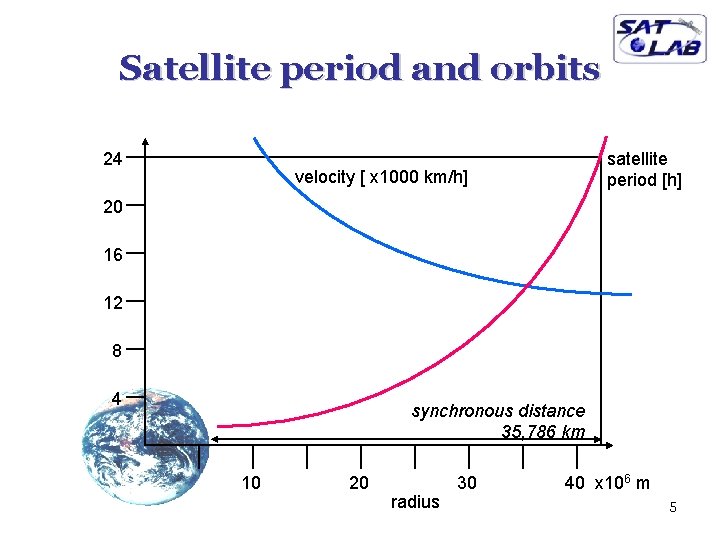
Basics • Satellites in circular orbits – attractive force Fg = m g (R/r)² – centrifugal force Fc = m r ² – m: mass of the satellite – R: radius of the earth (R = 6370 km) – r: distance to the center of the earth – g: acceleration of gravity (g = 9. 81 m/s²) – : angular velocity ( = 2 f, f: rotation frequency) • Stable orbit – Fg = F c 4
Satellite period and orbits 24 satellite period [h] velocity [ x 1000 km/h] 20 16 12 8 4 synchronous distance 35, 786 km 10 20 radius 30 40 x 106 m 5
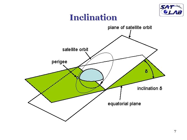
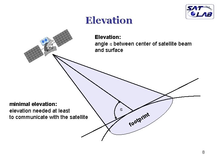
Basics q q q q elliptical or circular orbits complete rotation time depends on distance satellite-earth inclination: angle between orbit and equator elevation: angle between satellite and horizon LOS (Line of Sight) to the satellite necessary for connection high elevation needed, less absorption due to e. g. buildings Uplink: connection base station - satellite Downlink: connection satellite - base station typically separated frequencies for uplink and downlink – transponder used for sending/receiving and shifting of frequencies – transparent transponder: only shift of frequencies – regenerative transponder: additionally signal regeneration 6
Inclination plane of satellite orbit perigee d inclination d equatorial plane 7
Elevation: angle e between center of satellite beam and surface minimal elevation: elevation needed at least to communicate with the satellite e t in r p t foo 8
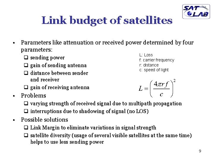
Link budget of satellites • Parameters like attenuation or received power determined by four parameters: q sending power q gain of sending antenna q distance between sender and receiver q gain of receiving antenna L: Loss f: carrier frequency r: distance c: speed of light • Problems q varying strength of received signal due to multipath propagation q interruptions due to shadowing of signal (no LOS) • Possible solutions q Link Margin to eliminate variations in signal strength q satellite diversity (usage of several visible satellites at the same time) helps to use less sending power 9
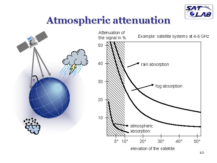
Atmospheric attenuation Attenuation of the signal in % Example: satellite systems at 4 -6 GHz 50 40 e rain absorption 30 fog absorption 20 10 atmospheric absorption 5° 10° 20° 30° elevation of the satellite 40° 50° 10
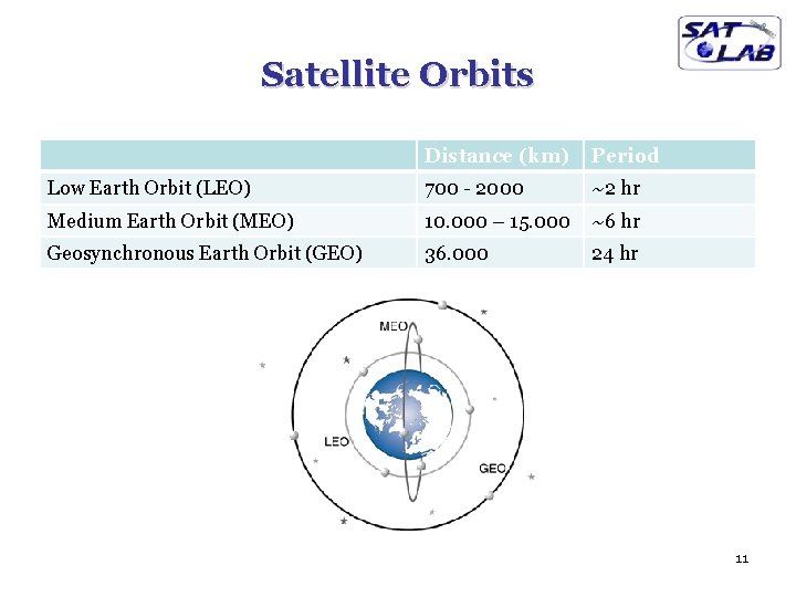
Satellite Orbits Distance (km) Period Low Earth Orbit (LEO) 700 - 2000 ~2 hr Medium Earth Orbit (MEO) 10. 000 – 15. 000 ~6 hr Geosynchronous Earth Orbit (GEO) 36. 000 24 hr 11
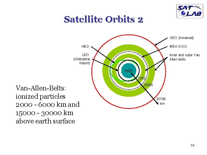
Satellite Orbits 2 GEO (Inmarsat) HEO MEO (ICO) LEO (Globalstar, Irdium) inner and outer Van Allen belts earth 1000 Van-Allen-Belts: ionized particles 2000 - 6000 km and 15000 - 30000 km above earth surface 10000 35768 km 12
GEO Satellites • • • No handover Altitude: ~35. 786 km. One-way propagation delay: 250 -280 ms 3 to 4 satellites for global coverage Mostly used in video broadcasting – Example: TURKSAT satellites • Another applications: Weather forecast, global communications, military applications • Advantage: well-suited for broadcast services • Disadvantages: Long delay, high free-space attenuation 13
MEO Satellites • • • Altitude: 10. 000 – 15. 000 km One-way propagation delay: 100 – 130 ms 10 to 15 satellites for global coverage Infrequent handover Orbit period: ~6 hr Mostly used in navigation – GPS, Galileo, Glonass • Communications: Inmarsat, ICO 14
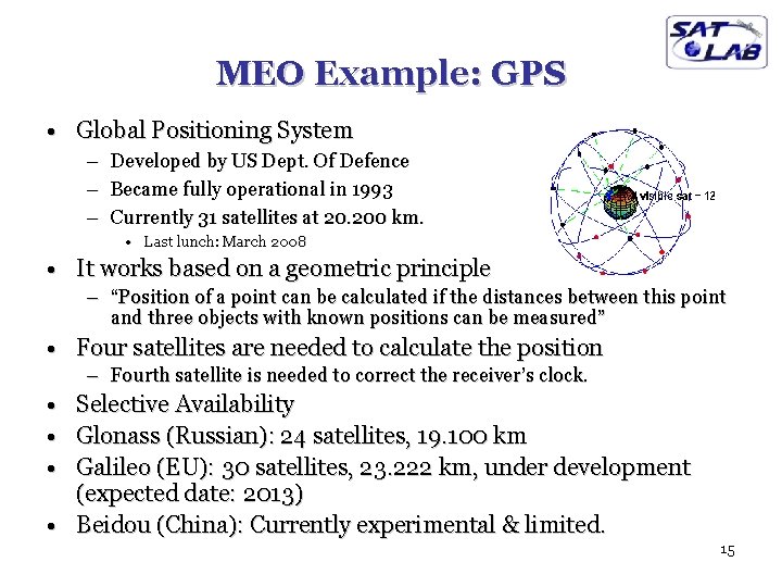
MEO Example: GPS • Global Positioning System – – – Developed by US Dept. Of Defence Became fully operational in 1993 Currently 31 satellites at 20. 200 km. • Last lunch: March 2008 • It works based on a geometric principle – “Position of a point can be calculated if the distances between this point and three objects with known positions can be measured” • Four satellites are needed to calculate the position – Fourth satellite is needed to correct the receiver’s clock. • • • Selective Availability Glonass (Russian): 24 satellites, 19. 100 km Galileo (EU): 30 satellites, 23. 222 km, under development (expected date: 2013) • Beidou (China): Currently experimental & limited. 15
LEO Satellites • • • Altitude: 700 – 2. 000 km One-way propagation delay: 5 – 20 ms More than 32 satellites for global coverage Frequent handover Orbit period: ~2 hr Applications: – Earth Observation • Google. Earth image providers (Digital. Globe, etc. ) • RASAT (First satellite to be produced solely in Turkey) – Communications • Globalstar, Iridium – Search and Rescue (SAR) • COSPAS-SARSAT 16
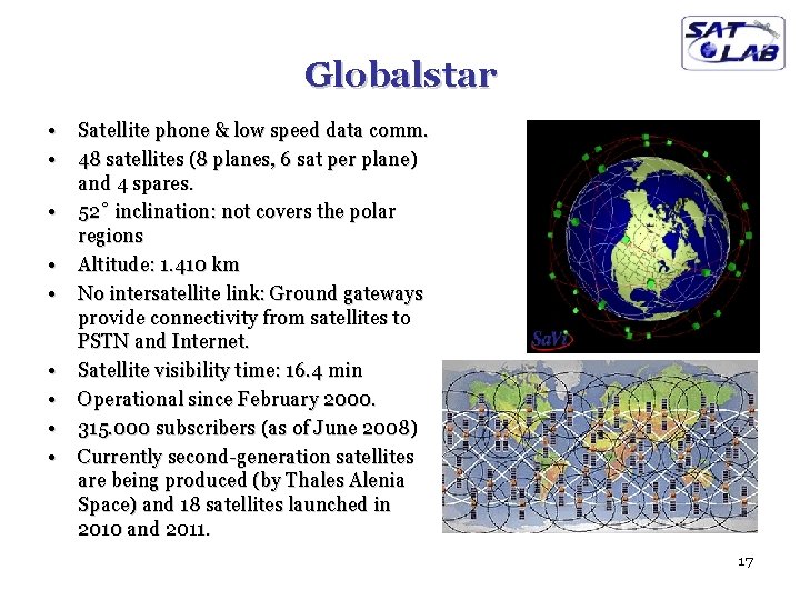
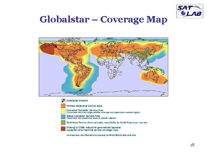
Globalstar • • • Satellite phone & low speed data comm. 48 satellites (8 planes, 6 sat per plane) and 4 spares. 52˚ inclination: not covers the polar regions Altitude: 1. 410 km No intersatellite link: Ground gateways provide connectivity from satellites to PSTN and Internet. Satellite visibility time: 16. 4 min Operational since February 2000. 315. 000 subscribers (as of June 2008) Currently second-generation satellites are being produced (by Thales Alenia Space) and 18 satellites launched in 2010 and 2011. 17
Globalstar – Coverage Map 18
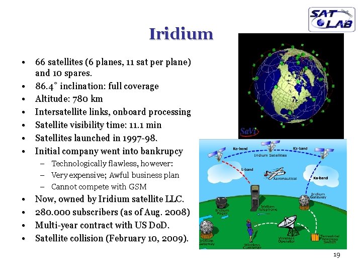
Iridium • • 66 satellites (6 planes, 11 sat per plane) and 10 spares. 86. 4˚ inclination: full coverage Altitude: 780 km Intersatellite links, onboard processing Satellite visibility time: 11. 1 min Satellites launched in 1997 -98. Initial company went into bankrupcy – – – • • Technologically flawless, however: Very expensive; Awful business plan Cannot compete with GSM Now, owned by Iridium satellite LLC. 280. 000 subscribers (as of Aug. 2008) Multi-year contract with US Do. D. Satellite collision (February 10, 2009). 19
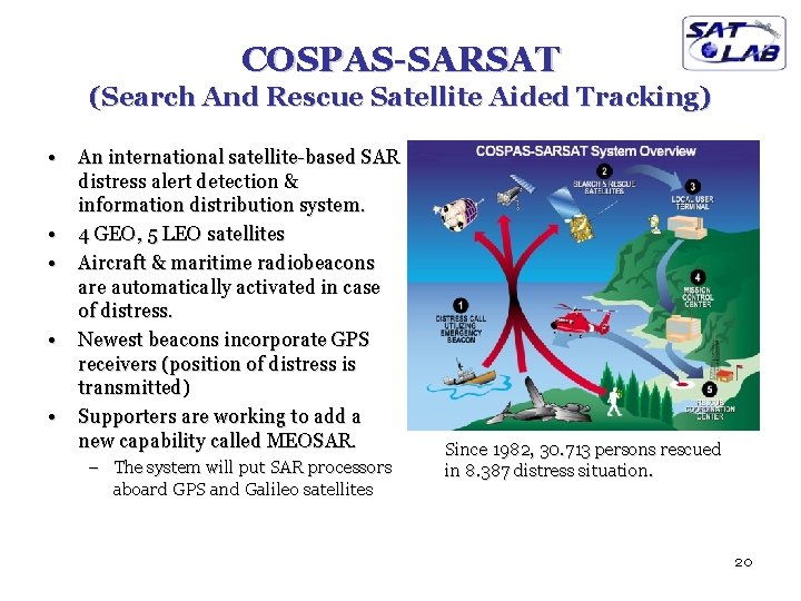
COSPAS-SARSAT (Search And Rescue Satellite Aided Tracking) • • • An international satellite-based SAR distress alert detection & information distribution system. 4 GEO, 5 LEO satellites Aircraft & maritime radiobeacons are automatically activated in case of distress. Newest beacons incorporate GPS receivers (position of distress is transmitted) Supporters are working to add a new capability called MEOSAR. – The system will put SAR processors aboard GPS and Galileo satellites Since 1982, 30. 713 persons rescued in 8. 387 distress situation. 20
Satellites - Overview • GEOs have good broadcasting capability, but long propagation delay. • LEOs offer low latency, low terminal power requirements. • Inter-satellite links and on-board processing for increased performance and better utilization of satellites – From flying mirrors to intelligent routers on sky. • Major problem with LEOs: Mobility of satellites – Frequent hand-over • Another important problem with satellites: – Infeasible to upgrade the technology, after the satellite is launched 21
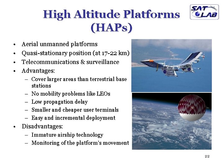
High Altitude Platforms (HAPs) • • Aerial unmanned platforms Quasi-stationary position (at 17 -22 km) Telecommunications & surveillance Advantages: – Cover larger areas than terrestrial base stations – No mobility problems like LEOs – Low propagation delay – Smaller and cheaper user terminals – Easy and incremental deployment • Disadvantages: – Immature airship technology – Monitoring of the platform’s movement 22
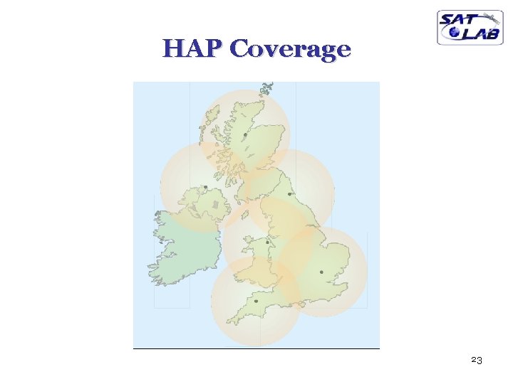
HAP Coverage 23
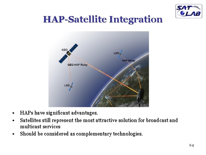
HAP-Satellite Integration • • • HAPs have significant advantages. Satellites still represent the most attractive solution for broadcast and multicast services Should be considered as complementary technologies. 24
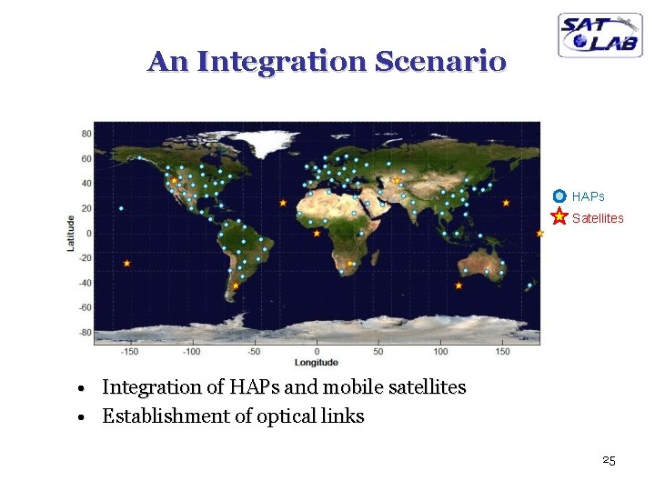
An Integration Scenario HAPs Satellites • Integration of HAPs and mobile satellites • Establishment of optical links 25
Optimal Assignment of Optical Links CONSTRAINTS: • A satellite and a HAP should have line of sight in order to communicate with each other. – Elevation angle between HAP and satellite should be larger than a certain εmin value. • Number of optical transmitters in satellites is limited. – A satellite can serve maximum of Hmax HAPs. • One to many relation between HAPs and satellites. AIMS: • As much HAP as possible should be served (Maximum utilization) • Average of elevation angles between HAPs and satellites should be maximized. 26
Optimal Assignment of Optical Links (cont. ) SOLUTION APPROACHES • This optimization problem can be represented as an Integer Linear Programming (ILP) problem • ILP solution approaches: Exclusive search, Branch-and-bound algorithms, etc. – Exponential time complexity – Not feasible for large networks • Optimization algorithm should be applied repeatedly – In periodic manner: every ∆t time unit – In event-driven manner: When a link becomes obsolete • Faster algorithm is necessary. • There exists a polynomial time solution approach 27
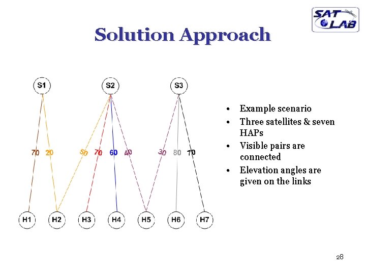
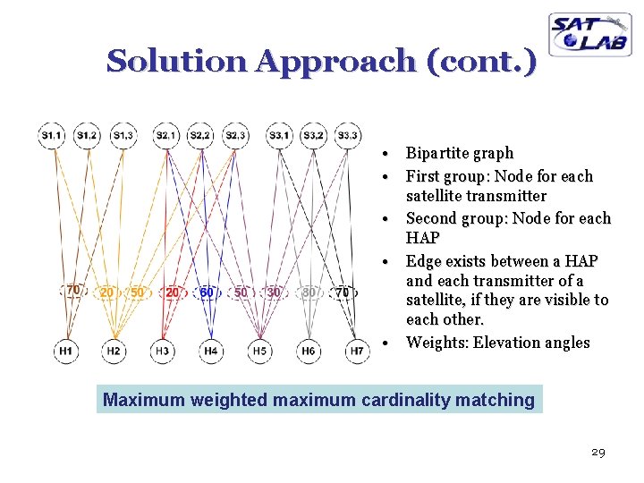
Solution Approach • • Example scenario Three satellites & seven HAPs Visible pairs are connected Elevation angles are given on the links 28
Solution Approach (cont. ) • • • Bipartite graph First group: Node for each satellite transmitter Second group: Node for each HAP Edge exists between a HAP and each transmitter of a satellite, if they are visible to each other. Weights: Elevation angles Maximum weighted maximum cardinality matching 29
Max Weighted Max Cardinality Matching • Matching: A subset of edges, such that no two edges share a common node. • Maximum cardinality matching: Matching with maximum number of edges. • Maximum weighted maximum cardinality matching: Maximum cardinality matching where the sum of the weights of the edges is maximum. • Hungarian Algorithm: O(n 3) 30
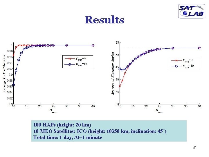
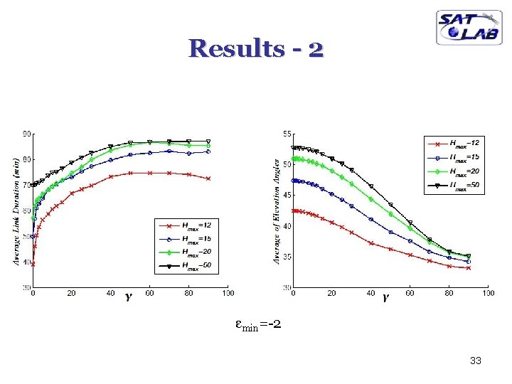
Results 100 HAPs (height: 20 km) 10 MEO Satellites: ICO (height: 10350 km, inclination: 45˚) Total time: 1 day, Δt=1 minute 31
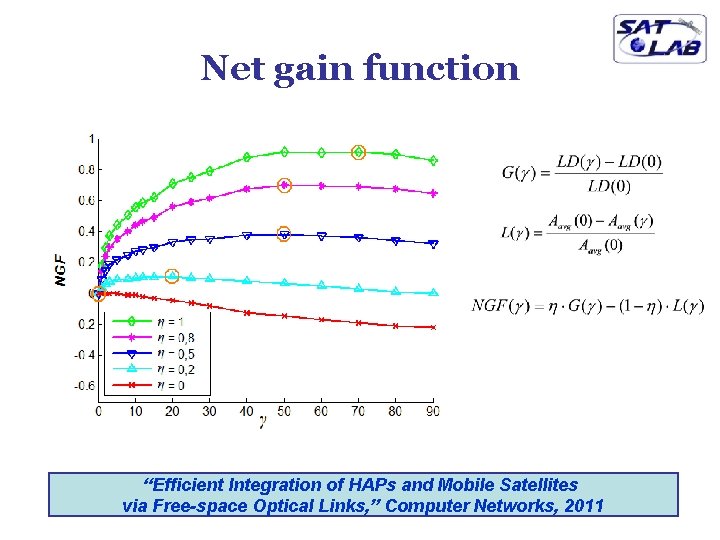
Increasing the Link Durations • Matching with maximum “average elevation angle” may result in frequent optical link switching – Switching from one satellite to another is an expensive operation. • Reduction of switching = Increasing the link durations • Method: Favor existing links with a particular amount γ – Weights of utilized edges are incremented by γ 32
Results - 2 εmin=-2 33
Net gain function “Efficient Integration of HAPs and Mobile Satellites via Free-space Optical Links, ” Computer Networks, 2011
More on Satellites • • Hand-over Satellite-fixed / Earth-fixed footprints Network Mobility Management Routing 35
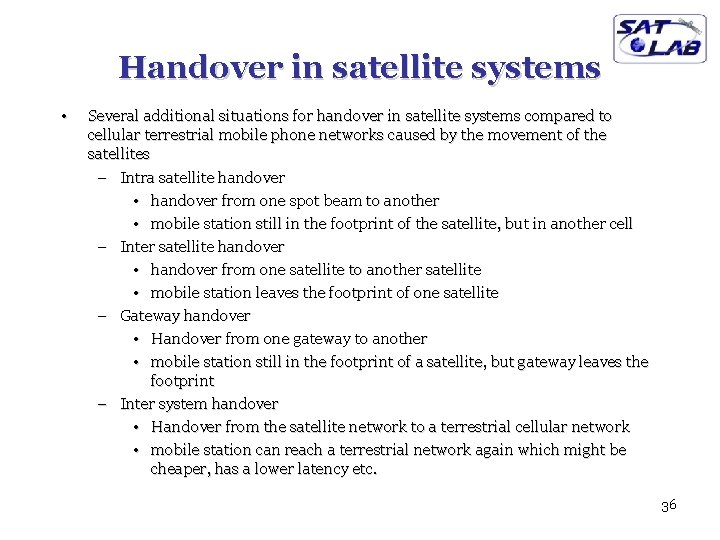
Handover in satellite systems • Several additional situations for handover in satellite systems compared to cellular terrestrial mobile phone networks caused by the movement of the satellites – Intra satellite handover • handover from one spot beam to another • mobile station still in the footprint of the satellite, but in another cell – Inter satellite handover • handover from one satellite to another satellite • mobile station leaves the footprint of one satellite – Gateway handover • Handover from one gateway to another • mobile station still in the footprint of a satellite, but gateway leaves the footprint – Inter system handover • Handover from the satellite network to a terrestrial cellular network • mobile station can reach a terrestrial network again which might be cheaper, has a lower latency etc. 36
Satellite-fixed vs Earth-fixed Footprints Satellite Fixed Footprints (asynchronous handoff) Earth Fixed Footprints (synchronous handoff) 37
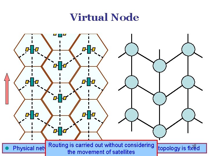
Virtual Node Routing is carried out without considering 38 A satellite corresponds in a time. l Physical network topology is dynamic to al. VN Virtual Node topology is fixed the movement of satellites
Routing • One solution: inter satellite links (ISL) q reduced number of gateways needed q forward connections or data packets within the satellite network as long as possible q only one uplink and one downlink per direction needed for the connection of two mobile phones • Problems: q more complex focusing of antennas between satellites q high system complexity due to moving routers q higher fuel consumption q thus shorter lifetime • Iridium and Teledesic planned with ISL • Other systems use gateways and additionally terrestrial networks 39
Features of Satellite Networks • Effects of satellite mobility – – Topology is dynamic. Topology changes are predictable and periodic. Traffic is very dynamic and non-homogeneous. Handovers are necessary. • Limitations and capabilities of satellites – Power and onboard processing capability are limited. – Implementing the state-of-the-art technology is difficult. – Satellites have a broadcast nature. • Nature of satellite constellations – Higher propagation delays. – Fixed number of nodes. – Highly symmetric and uniform structure. 40
Routing & Network MM • Considering these issues various routing & MM techniques are proposed. Main ideas are: – To handle dynamic topology changes with minimum overhead. – To prevent an outgoing call from dropping due to link handovers – To minimize length of the paths in terms of propagation delay and/or number of satellite hops. – To prevent congestion of some ISLs, while others are idle (Load balancing). – To perform traffic-based routing. – To provide better integration of satellite networks and terrestrial networks. – To perform efficient multicasting over satellites. “Exploring the Routing Strategies in Next-Generation Satellite Networks” IEEE Wireless Communications, 2007 41
Thank You Any questions?