COSC 3 P 92 Cosc 3 P 92


- Slides: 25
COSC 3 P 92 Cosc 3 P 92 Week 1 Lecture slides Psychiatrist to patient "You have nothing to worry about - anyone who can pay my bill is certainly not a failure. " 1
COSC 3 P 92 Class Room • Ground Rules • Cell Phones • My contact times – Open Policy – Email bockusd@brocku. ca 2
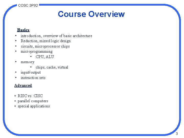
COSC 3 P 92 Course Overview Basics • • introduction, overview of basic architecture Reduction, mixed logic design circuits, microprocessor chips microprogramming • CPU, ALU memory • chips, cache, virtual input/output instruction sets Advanced • RISC vs CISC • parallel computers • special applications 3
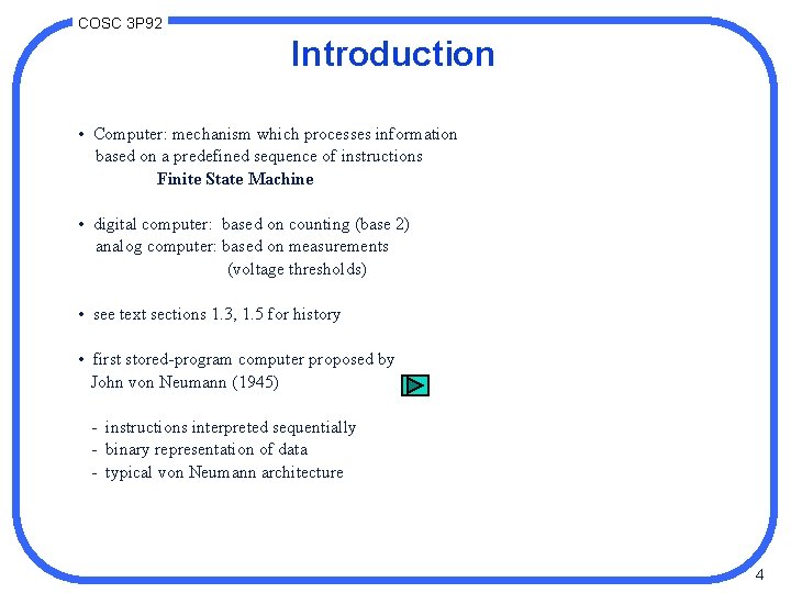
COSC 3 P 92 Introduction • Computer: mechanism which processes information based on a predefined sequence of instructions Finite State Machine • digital computer: based on counting (base 2) analog computer: based on measurements (voltage thresholds) • see text sections 1. 3, 1. 5 for history • first stored-program computer proposed by John von Neumann (1945) - instructions interpreted sequentially - binary representation of data - typical von Neumann architecture 4
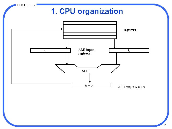
COSC 3 P 92 1. CPU organization registers A ALU input registers B ALU A + B ALU output register 5
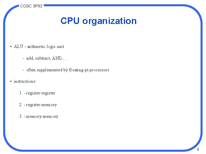
COSC 3 P 92 CPU organization • ALU - arithmetic logic unit - add, subtract, AND, . . . - often supplemented by floating-pt processors • instructions: 1 - register-register 2 - register-memory 3 - memory-memory 6
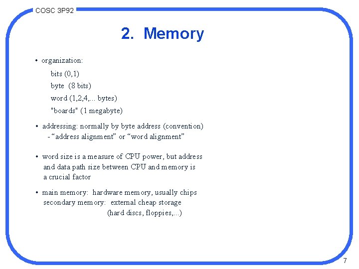
COSC 3 P 92 2. Memory • organization: bits (0, 1) byte (8 bits) word (1, 2, 4, . . . bytes) "boards" (1 megabyte) • addressing: normally by byte address (convention) - “address alignment” or “word alignment” • word size is a measure of CPU power, but address and data path size between CPU and memory is a crucial factor • main memory: hardware memory, usually chips secondary memory: external cheap storage (hard discs, floppies, . . . ) 7
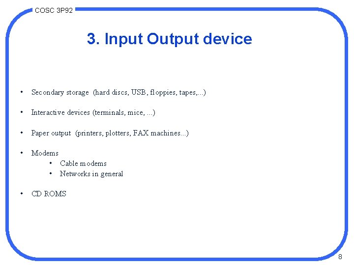
COSC 3 P 92 3. Input Output device • Secondary storage (hard discs, USB, floppies, tapes, . . . ) • Interactive devices (terminals, mice, . . . ) • Paper output (printers, plotters, FAX machines. . . ) • Modems • Cable modems • Networks in general • CD ROMS 8
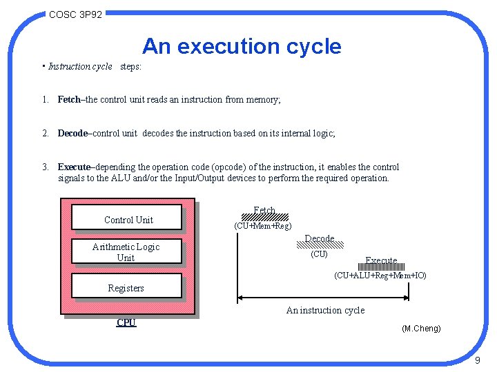
COSC 3 P 92 An execution cycle • Instruction cycle steps: 1. Fetch–the control unit reads an instruction from memory; 2. Decode–control unit decodes the instruction based on its internal logic; 3. Execute–depending the operation code (opcode) of the instruction, it enables the control signals to the ALU and/or the Input/Output devices to perform the required operation. Control Unit Arithmetic Logic Unit Fetch (CU+Mem+Reg) Decode (CU) Execute (CU+ALU+Reg+Mem+IO) Registers An instruction cycle CPU (M. Cheng) 9
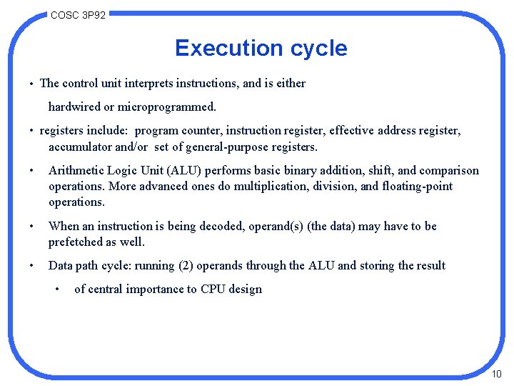
COSC 3 P 92 Execution cycle • The control unit interprets instructions, and is either hardwired or microprogrammed. • registers include: program counter, instruction register, effective address register, accumulator and/or set of general-purpose registers. • Arithmetic Logic Unit (ALU) performs basic binary addition, shift, and comparison operations. More advanced ones do multiplication, division, and floating-point operations. • When an instruction is being decoded, operand(s) (the data) may have to be prefetched as well. • Data path cycle: running (2) operands through the ALU and storing the result • of central importance to CPU design 10
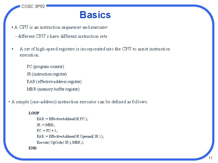
COSC 3 P 92 Basics • A CPU is an instruction sequencer and executor. - different CPU’s have different instruction sets • A set of high-speed registers is incorporated into the CPU to assist instruction execution. PC (program counter) IR (instruction register) EAR (effective address register) MBR (memory buffer register) • A simple (one-address) instruction executor can be defined as follows. LOOP EAR : = Effective. Address. Of( PC ); IR : = MBR; PC : = PC + 1; EAR : = Effective. Address. Of( Operand( IR ) ); Execute( Op. Code( IR ), MBR ); END 11
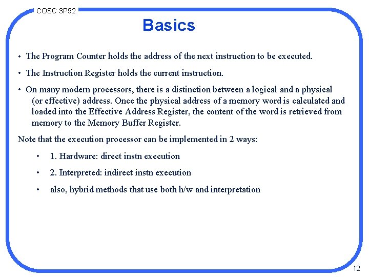
COSC 3 P 92 Basics • The Program Counter holds the address of the next instruction to be executed. • The Instruction Register holds the current instruction. • On many modern processors, there is a distinction between a logical and a physical (or effective) address. Once the physical address of a memory word is calculated and loaded into the Effective Address Register, the content of the word is retrieved from memory to the Memory Buffer Register. Note that the execution processor can be implemented in 2 ways: • 1. Hardware: direct instn execution • 2. Interpreted: indirect instn execution • also, hybrid methods that use both h/w and interpretation 12
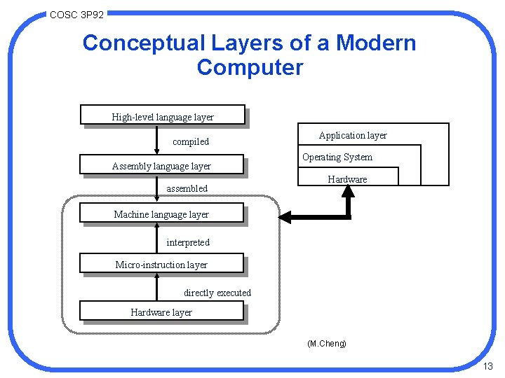
COSC 3 P 92 Conceptual Layers of a Modern Computer High-level language layer compiled Assembly language layer assembled Application layer Operating System Hardware Machine language layer interpreted Micro-instruction layer directly executed Hardware layer (M. Cheng) 13
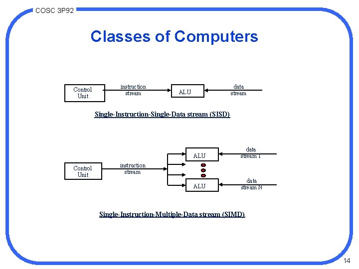
COSC 3 P 92 Classes of Computers Control Unit instruction stream data stream ALU Single-Instruction-Single-Data stream (SISD) Control Unit ALU data stream 1 ALU data stream N instruction stream Single-Instruction-Multiple-Data stream (SIMD) 14
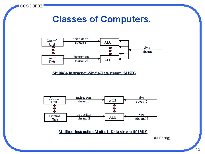
COSC 3 P 92 Classes of Computers. instruction stream 1 Control Unit ALU data stream instruction stream N Control Unit ALU Multiple-Instruction-Single-Data stream (MISD) Control Unit instruction stream 1 ALU data stream 1 Control Unit instruction stream N ALU data stream N Multiple-Instruction-Multiple-Data stream (MIMD) (M. Cheng) 15
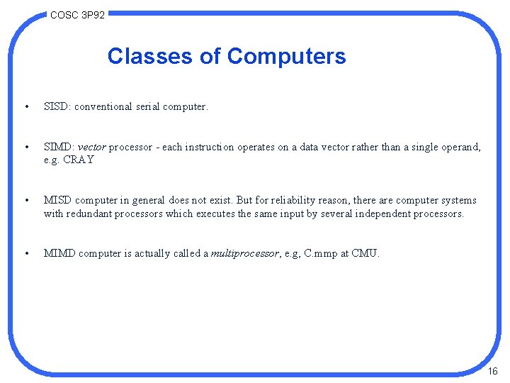
COSC 3 P 92 Classes of Computers • SISD: conventional serial computer. • SIMD: vector processor - each instruction operates on a data vector rather than a single operand, e. g. CRAY • MISD computer in general does not exist. But for reliability reason, there are computer systems with redundant processors which executes the same input by several independent processors. • MIMD computer is actually called a multiprocessor, e. g, C. mmp at CMU. 16
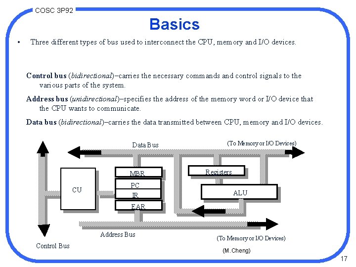
COSC 3 P 92 Basics • Three different types of bus used to interconnect the CPU, memory and I/O devices. Control bus (bidirectional)–carries the necessary commands and control signals to the various parts of the system. Address bus (unidirectional)–specifies the address of the memory word or I/O device that the CPU wants to communicate. Data bus (bidirectional)–carries the data transmitted between CPU, memory and I/O devices. Data Bus MBR CU PC IR (To Memory or I/O Devices) Registers ALU EAR Address Bus Control Bus (To Memory or I/O Devices) (M. Cheng) 17
COSC 3 P 92 Basics. • If a computer has an N-bit address bus, then it can address up to 2**N unique locations. • Every addressable unit may be of different sizes from one computer to another. It may be bit-addressable (e. g. , Burroughs B 1700), byte-addressable (e. g. , Intel 8086), or wordaddressable. (Note: There is no general agreement what a word size should be. ) • Typically is now defined as 2 m • When we speak of a computer of size N-bit, we usually refer to the size of its data bus. It is possible to have an 8 -bit computer with word size 16 -bit (e. g. , Intel 8088, Motorola 6800). 18
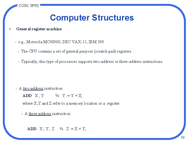
COSC 3 P 92 Computer Structures • General register machine - e. g. , Motorola MC 68000, DEC VAX-11, IBM 360 - The CPU contains a set of general purpose (scratch-pad) registers. - Typically, this type of processors supports two-address or three-address instructions. - A two-address instruction: ADD X , Y % Y : = Y + X; where X, Y and Z refer to a memory location or a register. - A three-address instruction: ADD X , Y, Z % Z : = X + Y; 19
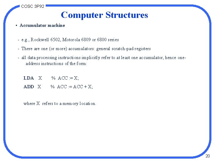
COSC 3 P 92 Computer Structures • Accumulator machine - e. g. , Rockwell 6502, Motorola 6809 or 6800 series - There are one (or more) accumulators: general scratch-pad registers - all data processing instructions implicitly refer to at least one accumulator, hence oneaddress instructions of the form: LDA X % ACC : = X; ADD X % ACC : = ACC + X; where X refers to a memory location. 20
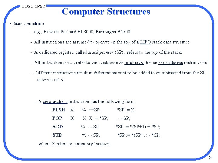
COSC 3 P 92 Computer Structures • Stack machine - e. g. , Hewlett-Packard HP 3000, Burroughs B 1700 - All instructions are assumed to operate on the top of a LIFO stack data structure - A dedicated register, called stack pointer (SP), refers to the top of the stack. - All instructions must refer to the stack pointer implicitly, hence zero-address instructions. - Different instructions result in different amount to be added to or subtracted from the SP automatically. - A zero-address instruction has the following form: PUSH X % ++SP; *SP : = X; POP X % X : = *SP; - - SP; ADD % - - SP; *SP : = *(SP+1) + *SP; SUB % - - SP; *SP : = *(SP+1) - *SP; where X refers to a memory location. 21
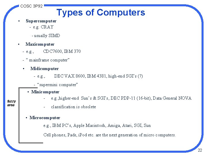
COSC 3 P 92 • Types of Computers Supercomputer - e. g. CRAY - usually SIMD • Maxicomputer - e. g. , CDC 7600, IBM 370 - “ mainframe computer” • Midicomputer - e. g. , DEC VAX 8600, IBM 4381, high-end SGI’s (? ) - “supermini computer” fuzzy area • Minicomputer - e. g. , higher-end Sun’s & SGI’s, DEC PDP-11 (16 -bit), Data General NOVA - classification is obsolete • Microcomputer e. g. , IBM PC’s, Apple Macintosh, Amiga, Atari, SGI, Sun Cell phones, Pads, i. Pod etc. are the next generation of micro computers. 22
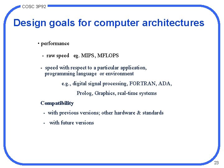
COSC 3 P 92 Design goals for computer architectures • performance - raw speed eg. MIPS, MFLOPS - speed with respect to a particular application, programming language or environment e. g. , digital signal processing, FORTRAN, ADA, Prolog, Graphics, real-time systems Compatibility - with previous versions; other hardware & standards - with future versions 23
COSC 3 P 92 Design goals for computer architectures. • ease of use: - easy to program e. g. , instruction set, interaction with external devices - easy to add peripherals e. g. , high-speed optical disks, a communication switching network 24
COSC 3 P 92 The end 26