Ch 28 wire open switch closed switch 2


- Slides: 26
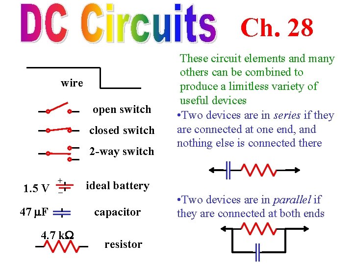
Ch. 28 wire open switch closed switch 2 -way switch 1. 5 V + – 47 F 4. 7 k These circuit elements and many others can be combined to produce a limitless variety of useful devices • Two devices are in series if they are connected at one end, and nothing else is connected there ideal battery capacitor resistor • Two devices are in parallel if they are connected at both ends
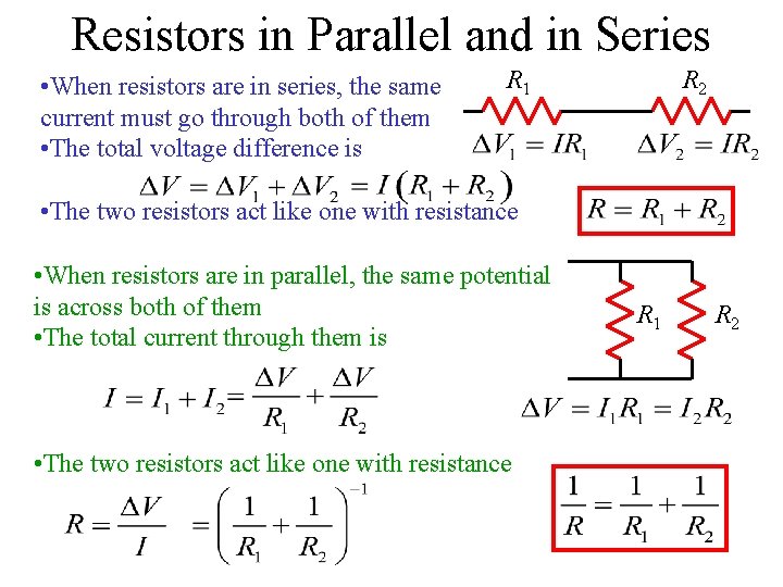
Resistors in Parallel and in Series • When resistors are in series, the same current must go through both of them • The total voltage difference is R 1 R 2 • The two resistors act like one with resistance • When resistors are in parallel, the same potential is across both of them • The total current through them is • The two resistors act like one with resistance R 1 R 2
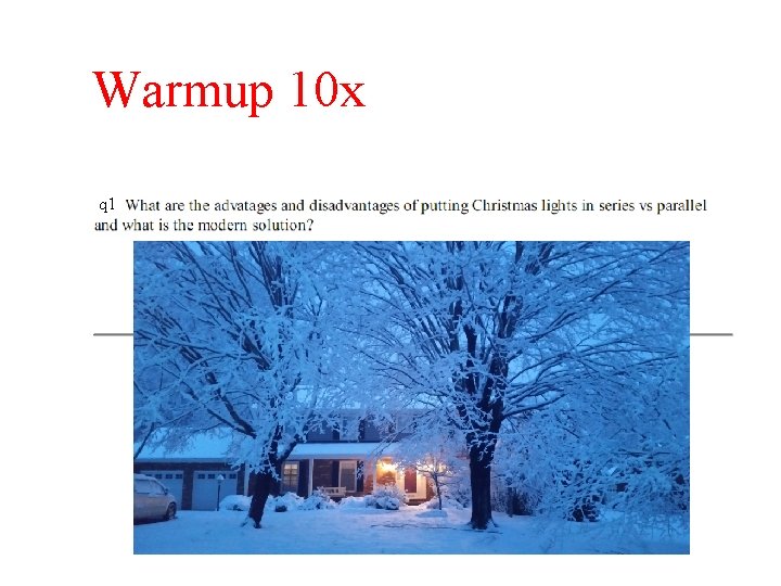
Warmup 10 x q 1
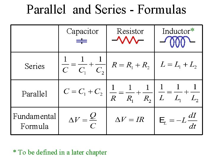
Parallel and Series - Formulas Capacitor Series Parallel Fundamental Formula * To be defined in a later chapter Resistor Inductor*
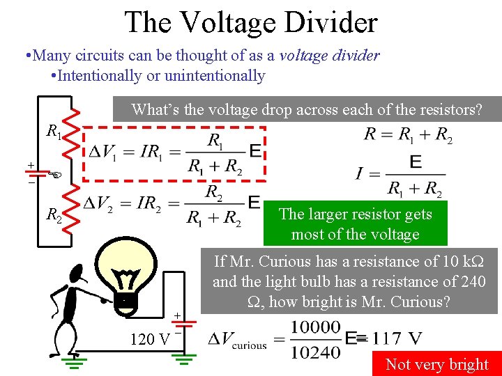
The Voltage Divider • Many circuits can be thought of as a voltage divider • Intentionally or unintentionally What’s the voltage drop across each of the resistors? R 1 + – E R 2 The larger resistor gets most of the voltage 120 V + – If Mr. Curious has a resistance of 10 k and the light bulb has a resistance of 240 , how bright is Mr. Curious? Not very bright
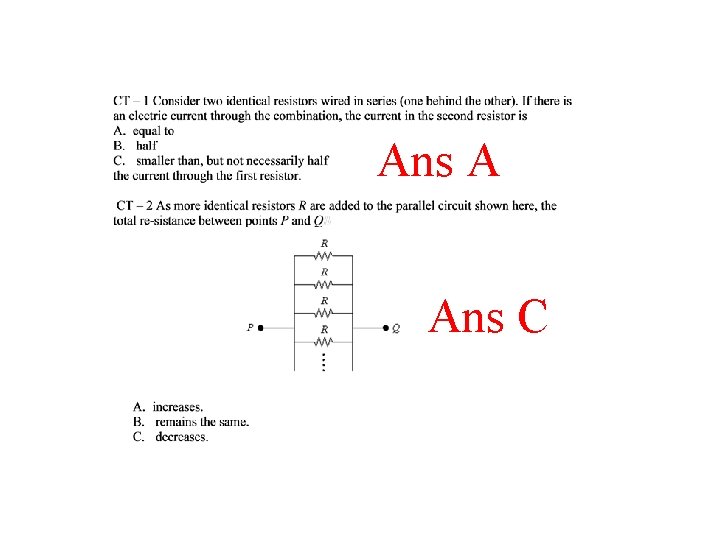
Ans A Ans C
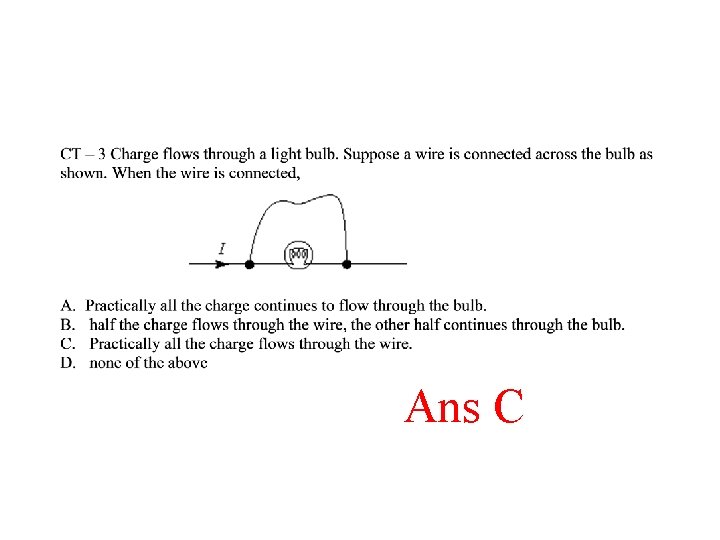
Ans C
Ans A
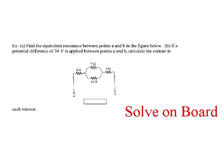
Solve on Board
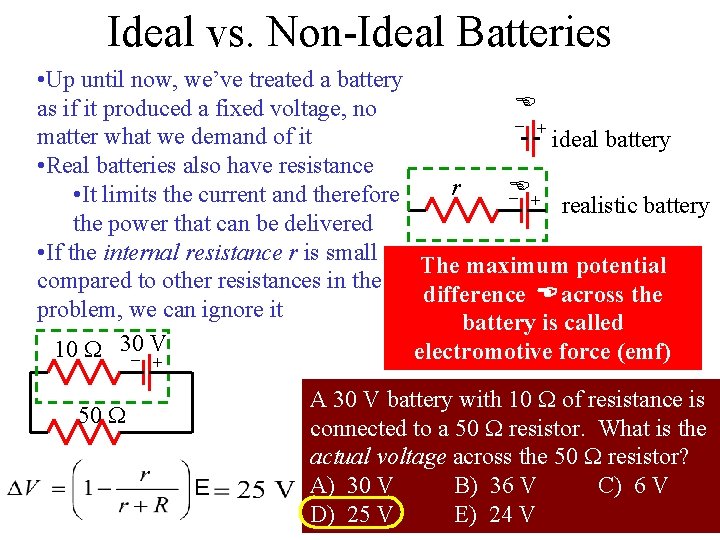
Ideal vs. Non-Ideal Batteries + – – + – 50 + • Up until now, we’ve treated a battery E as if it produced a fixed voltage, no matter what we demand of it ideal battery • Real batteries also have resistance r E • It limits the current and therefore realistic battery the power that can be delivered • If the internal resistance r is small The maximum potential compared to other resistances in the difference E across the problem, we can ignore it battery is called 10 30 V electromotive force (emf) A 30 V battery with 10 of resistance is connected to a 50 resistor. What is the actual voltage across the 50 resistor? A) 30 V B) 36 V C) 6 V D) 25 V E) 24 V
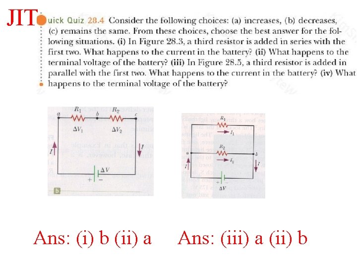
JIT Ans: (i) b (ii) a Ans: (iii) a (ii) b
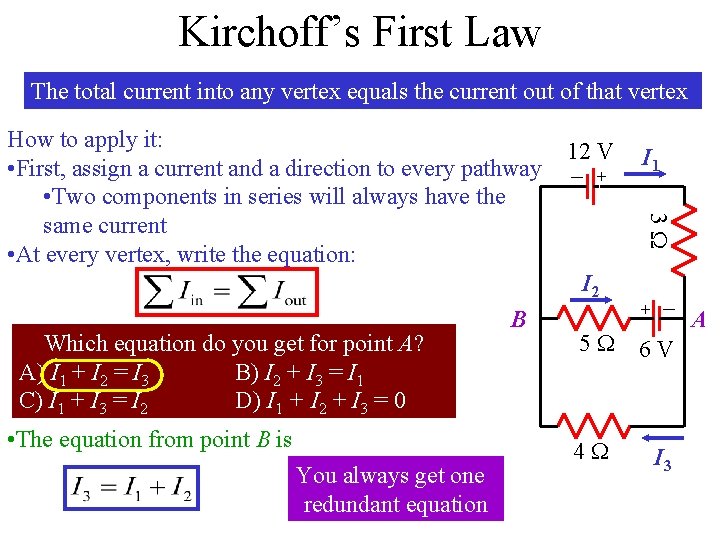
Kirchoff’s First Law The total current into any vertex equals the current out of that vertex 12 V – + Which equation do you get for point A? A) I 1 + I 2 = I 3 B) I 2 + I 3 = I 1 C) I 1 + I 3 = I 2 D) I 1 + I 2 + I 3 = 0 • The equation from point B is You always get one redundant equation – A 6 V + I 2 B I 1 3 How to apply it: • First, assign a current and a direction to every pathway • Two components in series will always have the same current • At every vertex, write the equation: 5 4 I 3
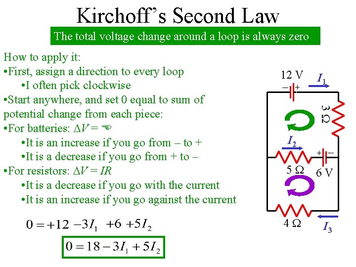
Kirchoff’s Second Law The total voltage change around a loop is always zero 12 V – + I 1 3 I 2 + How to apply it: • First, assign a direction to every loop • I often pick clockwise • Start anywhere, and set 0 equal to sum of potential change from each piece: • For batteries: V = E • It is an increase if you go from – to + • It is a decrease if you go from + to – • For resistors: V = IR • It is a decrease if you go with the current • It is an increase if you go against the current – 5 6 V 4 I 3
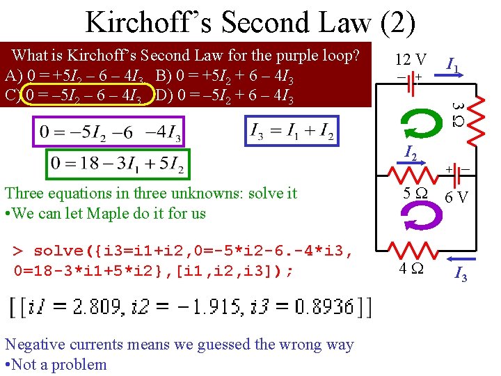
Kirchoff’s Second Law (2) 12 V – + I 1 3 What is Kirchoff’s Second Law for the purple loop? A) 0 = +5 I 2 – 6 – 4 I 3 B) 0 = +5 I 2 + 6 – 4 I 3 C) 0 = – 5 I 2 – 6 – 4 I 3 D) 0 = – 5 I 2 + 6 – 4 I 3 + I 2 Three equations in three unknowns: solve it • We can let Maple do it for us > solve({i 3=i 1+i 2, 0=-5*i 2 -6. -4*i 3, 0=18 -3*i 1+5*i 2}, [i 1, i 2, i 3]); Negative currents means we guessed the wrong way • Not a problem – 5 6 V 4 I 3
Solve on Board
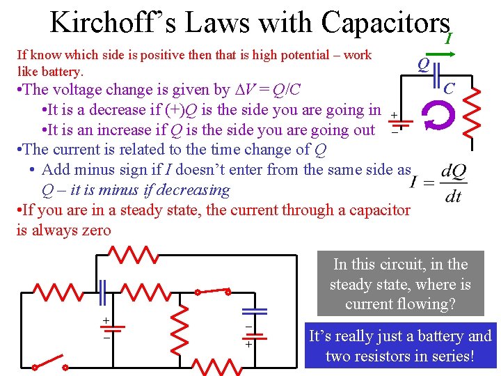
Kirchoff’s Laws with Capacitors. I If know which side is positive then that is high potential – work like battery. • The voltage change is given by V = Q/C • It is a decrease if (+)Q is the side you are going in + • It is an increase if Q is the side you are going out – • The current is related to the time change of Q • Add minus sign if I doesn’t enter from the same side as Q – it is minus if decreasing • If you are in a steady state, the current through a capacitor is always zero Q C In this circuit, in the steady state, where is current flowing? + – It’s really just a battery and two resistors in series!
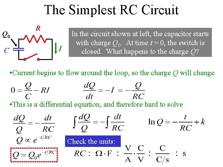
The Simplest RC Circuit Q 0 C R I In the circuit shown at left, the capacitor starts with charge Q 0. At time t = 0, the switch is closed. What happens to the charge Q? • Current begins to flow around the loop, so the charge Q will change • This is a differential equation, and therefore hard to solve Check the units:
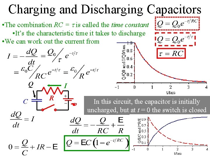
Charging and Discharging Capacitors • The combination RC = is called the time constant • It’s the characteristic time it takes to discharge • We can work out the current from Q C I R + – E In this circuit, the capacitor is initially uncharged, but at t = 0 the switch is closed
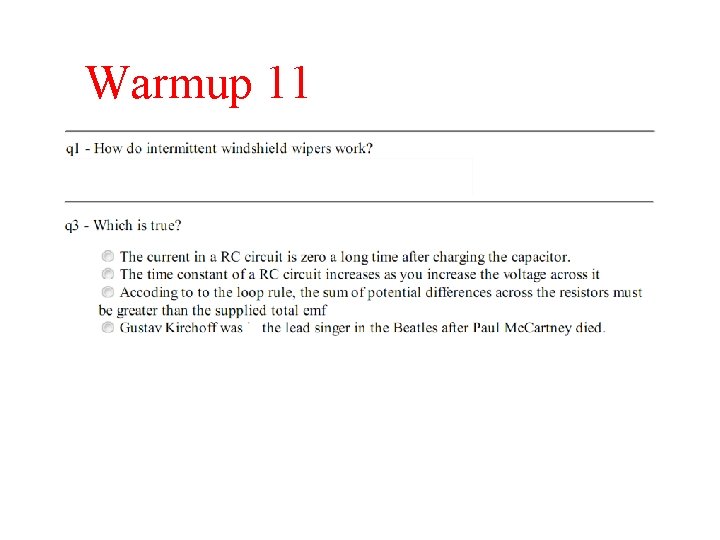
Warmup 11
Ans A
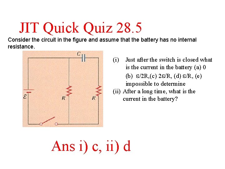
JIT Quick Quiz 28. 5 Consider the circuit in the figure and assume that the battery has no internal resistance. (i) Just after the switch is closed what is the current in the battery (a) 0 (b) e/2 R, (c) 2 e/R, (d) e/R, (e) impossible to determine (ii) After a long time, what is the current in the battery? Ans i) c, ii) d
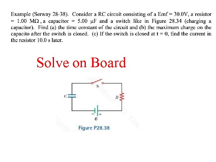
Solve on Board
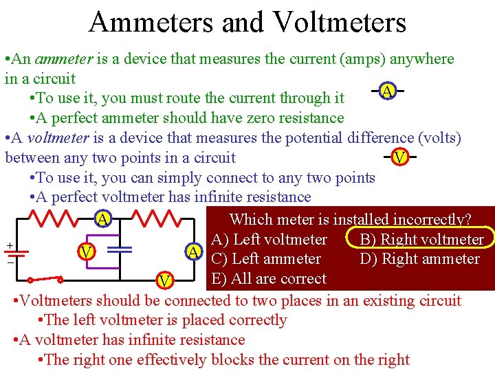
Ammeters and Voltmeters • An ammeter is a device that measures the current (amps) anywhere in a circuit A • To use it, you must route the current through it • A perfect ammeter should have zero resistance • A voltmeter is a device that measures the potential difference (volts) between any two points in a circuit V • To use it, you can simply connect to any two points • A perfect voltmeter has infinite resistance A Which meter is installed incorrectly? A) Left voltmeter B) Right voltmeter + V A C) Left ammeter D) Right ammeter – E) All are correct V • Voltmeters should be connected to two places in an existing circuit • The left voltmeter is placed correctly • A voltmeter has infinite resistance • The right one effectively blocks the current on the right
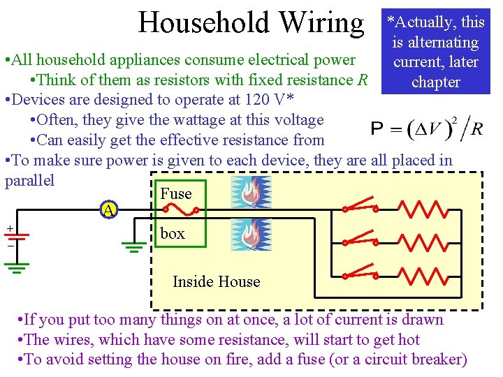
Household Wiring *Actually, this is alternating current, later chapter • All household appliances consume electrical power • Think of them as resistors with fixed resistance R • Devices are designed to operate at 120 V* • Often, they give the wattage at this voltage • Can easily get the effective resistance from • To make sure power is given to each device, they are all placed in parallel Fuse A + box – Inside House • If you put too many things on at once, a lot of current is drawn • The wires, which have some resistance, will start to get hot • To avoid setting the house on fire, add a fuse (or a circuit breaker)
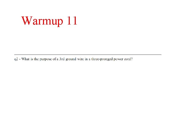
Warmup 11
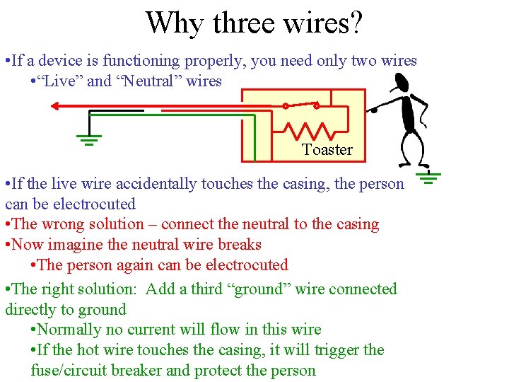
Why three wires? • If a device is functioning properly, you need only two wires • “Live” and “Neutral” wires Toaster • If the live wire accidentally touches the casing, the person can be electrocuted • The wrong solution – connect the neutral to the casing • Now imagine the neutral wire breaks • The person again can be electrocuted • The right solution: Add a third “ground” wire connected directly to ground • Normally no current will flow in this wire • If the hot wire touches the casing, it will trigger the fuse/circuit breaker and protect the person