Camshafts and Valve Trains NATEF Task List P1


- Slides: 26

Camshafts and Valve Trains

NATEF Task List P-1: 1. Adjust valves (mechanical and hydraulic lifters). 2. Inspect and replace timing belts (chains), overhead camdrive sprockets, and tensioners; check belt/chain tension; adjust as necessary. 3. Establish camshaft(s) timing and cam sensor indexing according to manufacturer’s specifications and procedures.

P-2 1. Inspect pushrods, rocker arm pivots and shafts for wear, bending, cracks, looseness, and blocked oil passages (orifices); determine necessary action. 2. Inspect hydraulic or mechanical lifters; determine necessary action. 3. Inspect camshaft drives (including gear wear and backlash, sprocket and chain wear); determine necessary action. 4. Inspect camshaft for runout, journal wear and lobe wear. 5. Inspect auxiliary (balance, intermediate, idler, counterbalance or silencer) shaft(s); inspect shaft(s) and support bearings for damage and wear; determine necessary action; reinstall and time. 6. P-3 7. Inspect camshaft bearing surface for wear, damage, out-of-round, and alignment; determine necessary action. 8. Inspect and measure camshaft bearings for wear, damage, out-ofround, and alignment; determine necessary action.

Cam and camshaft terms (nomenclature).

The lobe lift is the amount the cam lobe lifts the lifter. Because the rocker arm adds to this amount, the entire valve train has to be considered when selecting a camshaft that has the desired lift and duration.

The ramps on the cam lobe allow the valves to be opened and closed quickly yet under control to avoid damaging valve train components, especially at high engine speeds.

In many engines, the camshaft drives the distributor and the oil pump through a shaft from the end of the distributor.

The fuel pump plunger rides on the camshaft eccentric.

Pushrod Lifter Inside view of an overhead valve pushrod engine. TECH TIP 1 TECH TIP 2

The larger camshaft gear is usually made from fiber and given a helical cut to help reduce noise. By making the camshaft gear twice as large as the crankshaft gear, the camshaft rotates one revolution for every two of the crankshaft.

Courtesy of Sealed Power Corporation, Perfect Circle Products The industry standard for when to replace a timing chain and gears is when ½ inch (13 millimeters) or more of slack is measured in the chain. However, it is best to replace the timing chain and gear anytime the camshaft is replaced or the engine is disassembled for repair or overhaul.

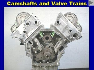
Typical dual overhead camshaft V-type engine that uses one primary timing chain and two secondary chains. Diagnostic Story

Many engines are of the interference design. If the timing belt (or chain) breaks, the piston still moves up and down in the cylinder while the valves remain stationary. With a freewheeling design, nothing is damaged, but in an interference engine, the valves are often bent.

A 1. 5: 1 ratio rocker arm means that dimension A is 1. 5 times the length of B. Therefore, if the pushrod is moved up 0. 400 inch by the camshaft lobe, the valve will be pushed down (opened) 0. 400 inch X 1. 5, or 0. 600 inch.

A new timing chain installed on a well worn engine. Diagnostic Story

Some overhead camshaft engines use a bucket-type cam follower which uses valve lash adjusting shims to adjust the valve lash. A special tool is usually required to compress the valve spring so that a magnet can remove the shim.

Some engines today use rocker shafts to support rocker arms such as the V 6 engine with a single overhead camshaft in the center of the cylinder head. TECH TIP

Typical cam timing diagram.

Degree wheel indicating where the piston stopped near top dead center. By splitting the difference between the two readings, the true TDC (28°) can be located on the degree wheel.

Typical valve timing diagram showing the intake lobe centerline at 106° ATDC. High Performance Tip

Lifters or tappets are made in two styles: flat bottom and roller.

A cross-sectional view of a typical flat -bottomed hydraulic lifter.

Cutaway view of a hydraulic lifter. TECH TIP

Hydraulic lash adjusters (HLA) are built into the rocker arm on some OHC engines.

Hydraulic lifters are also built into buckettype lifters on many OHC engines.

End of show To correctly adjust the valve clearance (lash), position the camshaft on the base circle of the camshaft lobe for the valve being adjusted. Remove all clearance by spinning the pushrod and tightening the nut unit all clearance is removed. The adjusting nut is then tightened one complete revolution. This is what is meant by the term “zero lash plus 1 turn. ”
 Valves
 Servo valve function
 Maglev pros and cons
 Who trains employees that work on scaffolds
 Rail big data analytics
 Rbp trains chris
 Bear superlative degree
 Combined pulley
 Les trains de la vie
 Grand corp malade le train
 Simple gear train definition
 Holonomic drive train
 Tank drive vex
 Unctad trains
 Ethicon taskit
 Tiered task bias task
 Learning task 2 look around your home
 Ujtl
Ujtl B31q
B31q Mission essential task list
 List the primitives that specify a data mining task.
 B31q task list
 Axiom meaning in maths
 Advantage of linked list
 Introduction to linked list
 List h shows account.
 Single linked list adalah yang paling dari semua varian
