AOI Logic Implementation Digital Electronics 2014 Project Lead

- Slides: 16
AOI Logic Implementation Digital Electronics © 2014 Project Lead The Way, Inc.
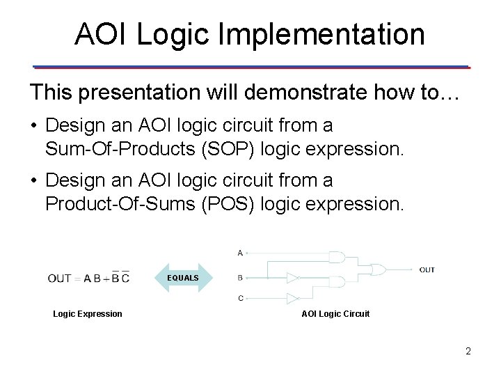
AOI Logic Implementation This presentation will demonstrate how to… • Design an AOI logic circuit from a Sum-Of-Products (SOP) logic expression. • Design an AOI logic circuit from a Product-Of-Sums (POS) logic expression. EQUALS Logic Expression AOI Logic Circuit 2
Designing (AOI) Sum of Product (SOP) Logic Circuits Design Steps • Implement each Minterm in the logic expression with an AND gate with the same number of inputs as there are variables in the Minterm. (i. e. , AB = 2 input gate, ABC = 3 input gate, ABCD = 4 input gate, etc. ) • OR together the outputs of the AND gates to produce the logic expression. • If necessary, gates can be cascaded to create gates with more inputs. 3
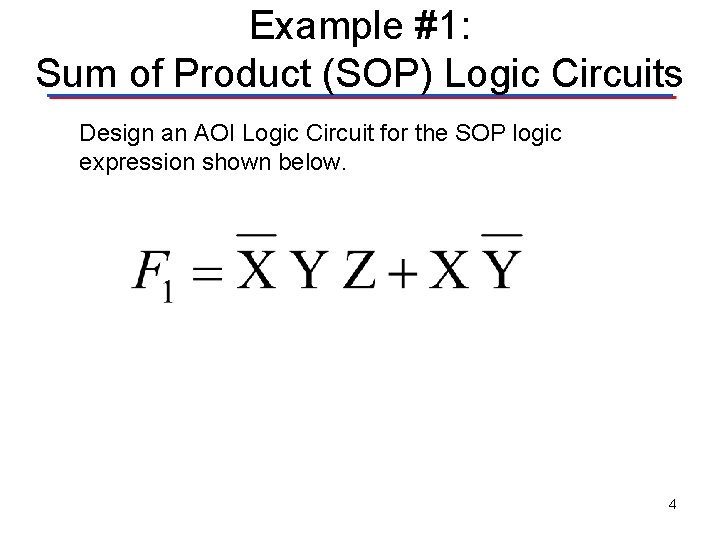
Example #1: Sum of Product (SOP) Logic Circuits Design an AOI Logic Circuit for the SOP logic expression shown below. 4
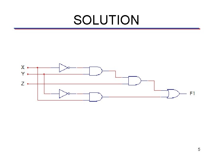
SOLUTION 5
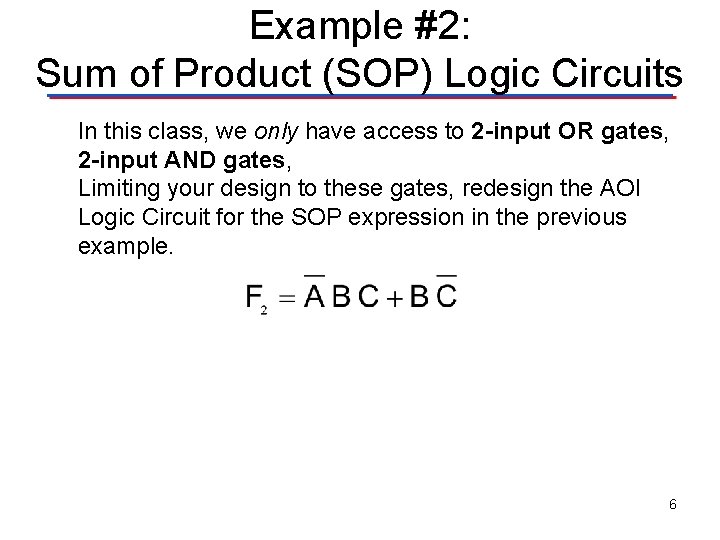
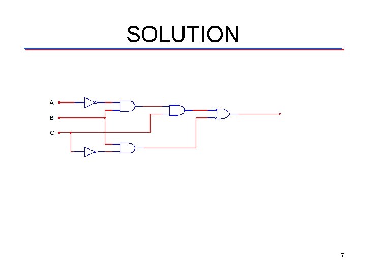
Example #2: Sum of Product (SOP) Logic Circuits In this class, we only have access to 2 -input OR gates, 2 -input AND gates, Limiting your design to these gates, redesign the AOI Logic Circuit for the SOP expression in the previous example. 6
SOLUTION 7
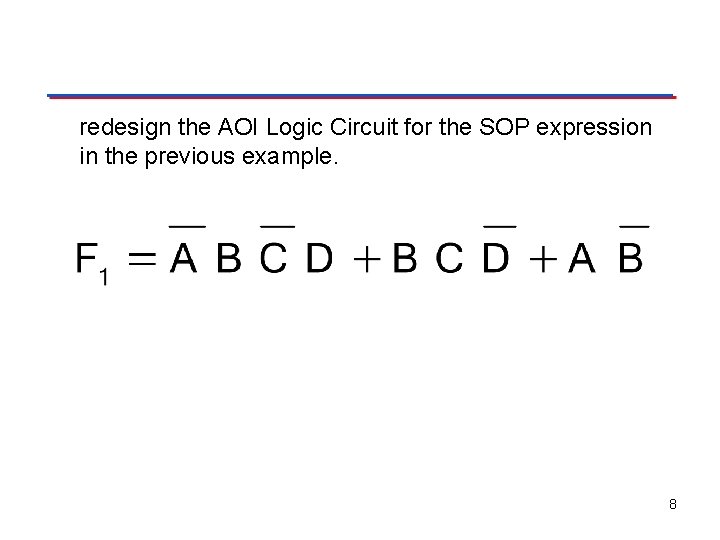
redesign the AOI Logic Circuit for the SOP expression in the previous example. 8
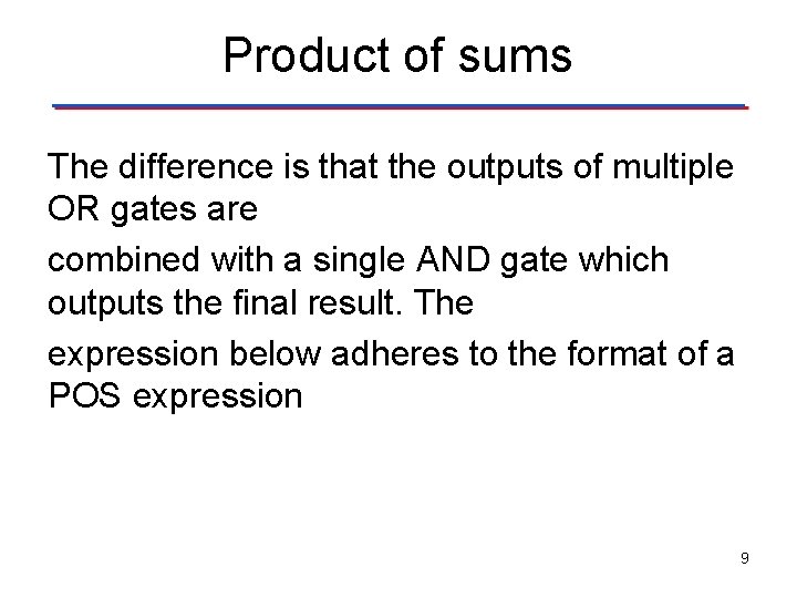
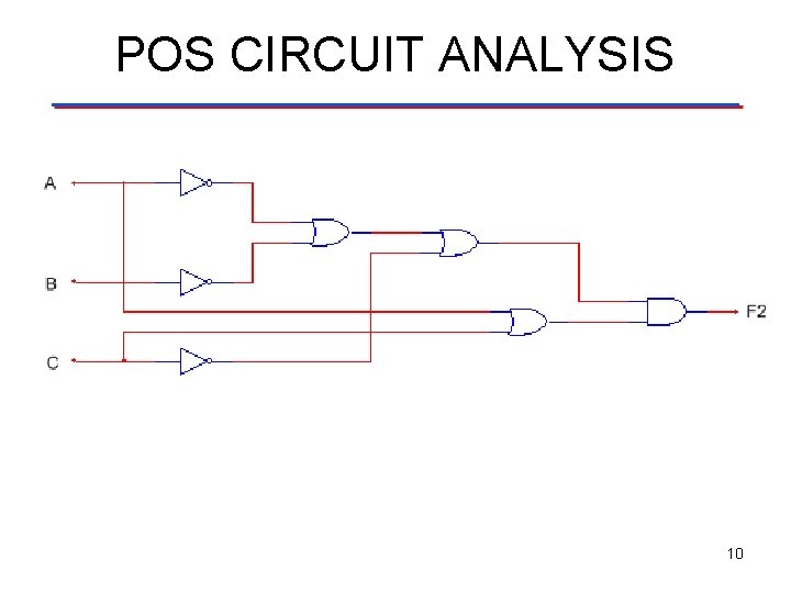
Product of sums The difference is that the outputs of multiple OR gates are combined with a single AND gate which outputs the final result. The expression below adheres to the format of a POS expression 9
POS CIRCUIT ANALYSIS 10
Designing (AOI) Product of Sum (POS) Logic Circuits Design Steps • Implement each Maxterm in the logic expression with an OR gate with the same number of inputs as there are variables in the Maxterm. (i. e. , A+B = 2 input gate, A+B+C = 3 input gate, A+B+C+D = 4 input gate, etc. ) • AND together the outputs of the OR gates to produce the logic expression. • If necessary, gates can be cascaded to create gates with more inputs. 11
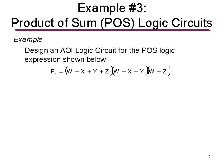
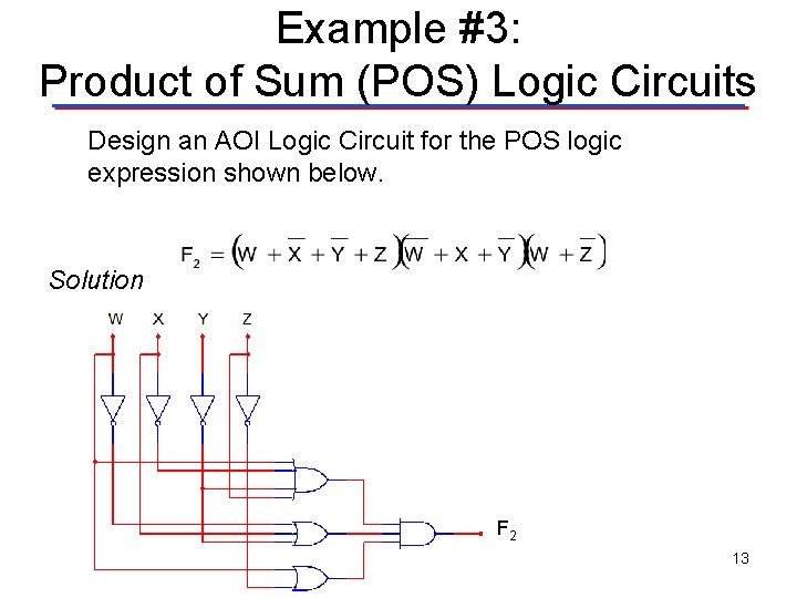
Example #3: Product of Sum (POS) Logic Circuits Example Design an AOI Logic Circuit for the POS logic expression shown below. 12
Example #3: Product of Sum (POS) Logic Circuits Design an AOI Logic Circuit for the POS logic expression shown below. Solution F 2 13
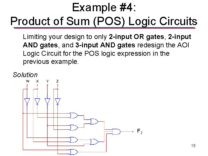
Example #4: Product of Sum (POS) Logic Circuits Limiting your design to only 2 -input OR gates, 2 -input AND gates, and 3 -input AND gates redesign the AOI Logic Circuit for the POS logic expression in the previous example. 14
Example #4: Product of Sum (POS) Logic Circuits Limiting your design to only 2 -input OR gates, 2 -input AND gates, and 3 -input AND gates redesign the AOI Logic Circuit for the POS logic expression in the previous example. Solution F 2 15
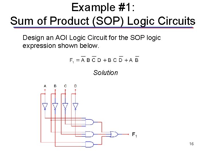
Example #1: Sum of Product (SOP) Logic Circuits Design an AOI Logic Circuit for the SOP logic expression shown below. Solution F 1 16