An Architecture for Differentiated Services RFC 2475 Introduction
- Slides: 31
An Architecture for Differentiated Services RFC 2475
Introduction Diffserv architecture is to implement scalable service in the Internet A Service defines some significant characteristics of packet transmission such as : n throughput, delay, jitter, loss Service differentiation is desired to accommodate heterogeneous app. requirements and user expectations
Introduction Diffserv architecture is compose of a number of functional elements implemented in network nodes: n n n A small set of per-hop forwarding behavior Packet classification functions Traffic conditioning functions Complex classification and conditioning functions are only at boundary nodes n achieves scalability
Requirements Accommodate a wide variety of services and provisioning policies Allow decoupling of the service form the particular app. in use Work with existing app. without the need for the changes of the app. Decouple traffic conditioning and service provisioning functions form forwarding behaviors within core nodes
Requirements Should not depend on hop-by-hop app. signaling Require only a small set of forwarding behaviors Avoid per-microflow or per-customer state within core network nodes Utilize only aggregated classification state within core network nodes
Requirements Permit simple packet classification implementations in core network nodes Permit reasonable interoperability with non-DS-compliant network nodes Accommodate incremental deployment
Diffserv Architectural Model The simple model is: n Traffic entering a network is classified and possibly conditioned at the boundaries of the network, and assigned to different behavior aggregates Behavior aggregate is identified by a single DS codepoint Packets are forwarded according to the per-hop behavior associated with the DS codepoint in the core network
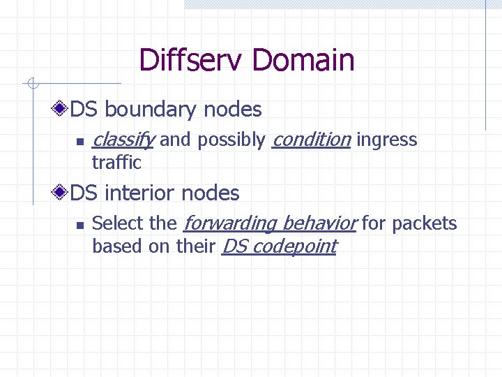
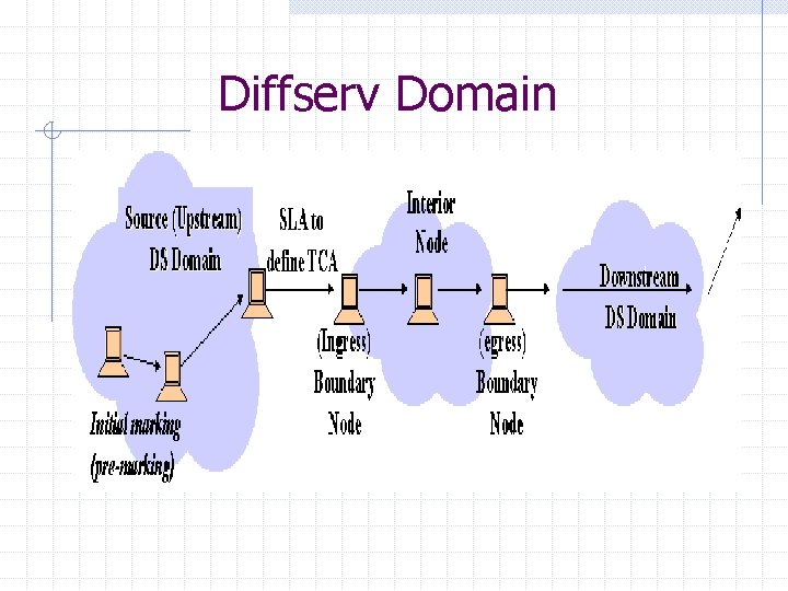
Diffserv Domain DS boundary nodes n classify and possibly condition ingress traffic DS interior nodes n Select the forwarding behavior for packets based on their DS codepoint
Diffserv Domain
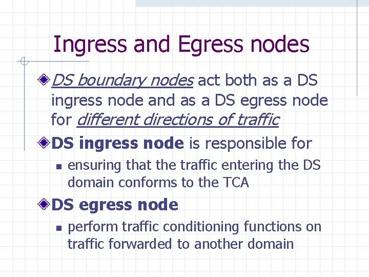
Ingress and Egress nodes DS boundary nodes act both as a DS ingress node and as a DS egress node for different directions of traffic DS ingress node is responsible for n ensuring that the traffic entering the DS domain conforms to the TCA DS egress node n perform traffic conditioning functions on traffic forwarded to another domain
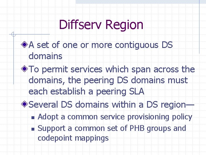
Diffserv Region A set of one or more contiguous DS domains To permit services which span across the domains, the peering DS domains must each establish a peering SLA Several DS domains within a DS region— n n Adopt a common service provisioning policy Support a common set of PHB groups and codepoint mappings
Traffic classification and conditioning Packet classification policy n Identify the subset of traffic Traffic conditioning performs: n n Metering Shaping Policing Remarking
Classifiers Select packets in a traffic stream based on the content of some portion of the packet header Two types of classifiers— n BA (Behavior Aggregate) classifier w Classify the packets based on codepoint only n MF (Multi-Field) classifier w Classify the packets based on the value of a combination of one or more header fields
Traffic profiles Specifies the temporal properties of a traffic stream selected by a classifier Provides rules for determining whether a particular packet is in-profile or out-of -profile Example: n n codepoint=X, use token-bucket r, b r—rate ; b—burst size
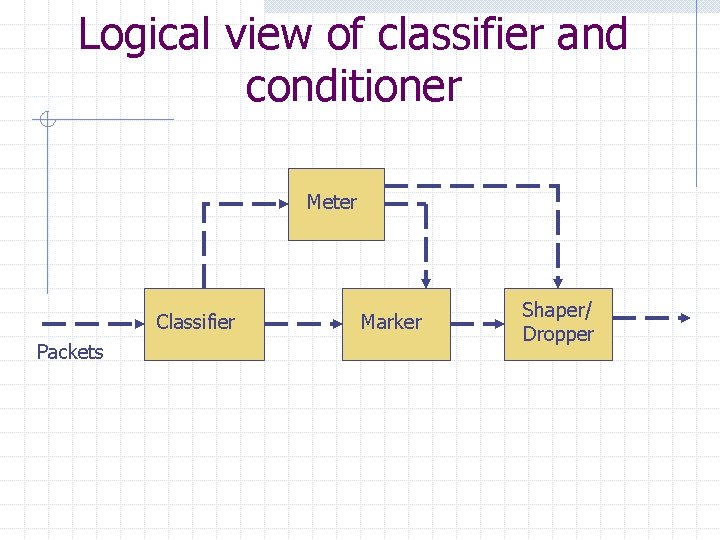
Traffic conditioners A traffic conditioner may contain the following elements: n n Meter Marker Shaper Dropper A traffic stream is selected by a classifier Classifier steers the packets to a logical instance of a traffic conditioner
Logical view of classifier and conditioner Meter Classifier Packets Marker Shaper/ Dropper
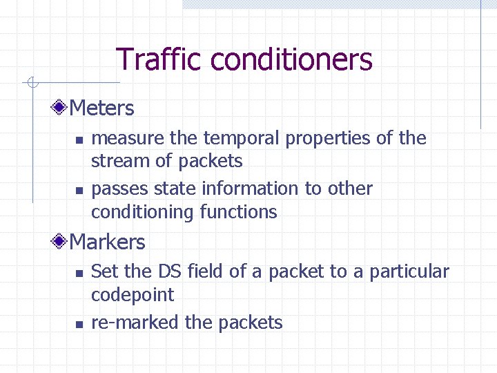
Traffic conditioners Meters n n measure the temporal properties of the stream of packets passes state information to other conditioning functions Markers n n Set the DS field of a packet to a particular codepoint re-marked the packets
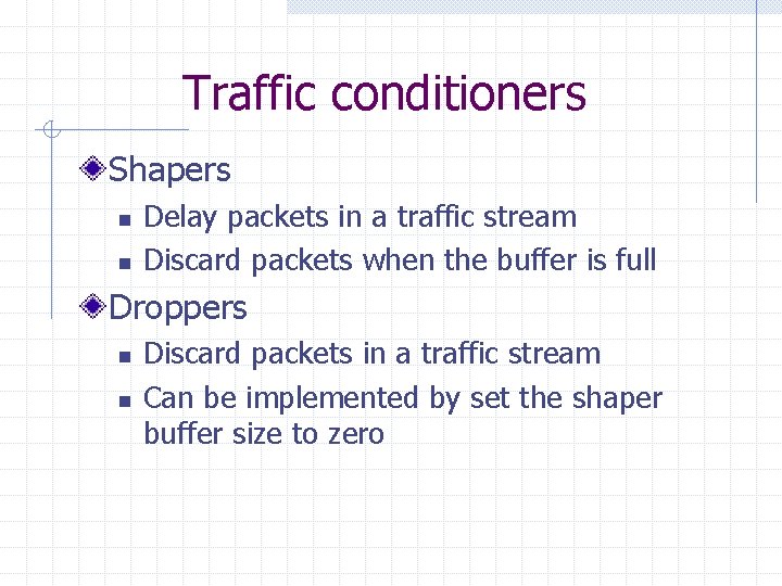
Traffic conditioners Shapers n n Delay packets in a traffic stream Discard packets when the buffer is full Droppers n n Discard packets in a traffic stream Can be implemented by set the shaper buffer size to zero
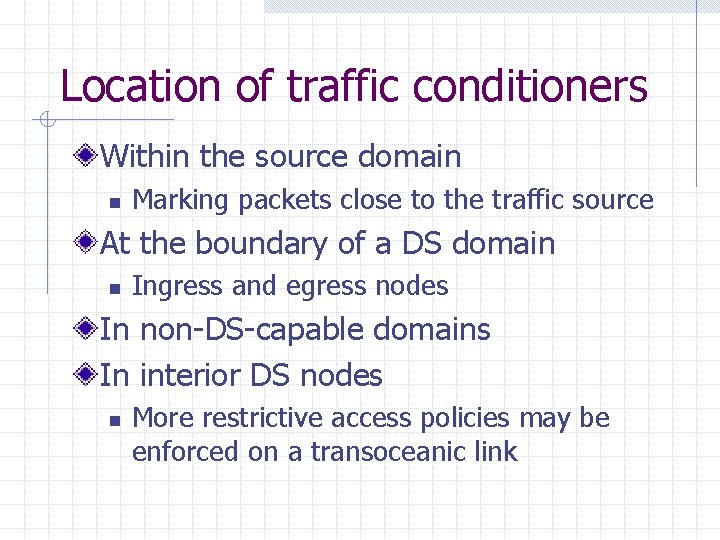
Location of traffic conditioners Within the source domain n Marking packets close to the traffic source At the boundary of a DS domain n Ingress and egress nodes In non-DS-capable domains In interior DS nodes n More restrictive access policies may be enforced on a transoceanic link
Per-Hop Behaviors The externally observable behavior of a DS node applied to a particular DS behavior aggregate PHBs are implemented in nodes by means of some buffer management and packet scheduling mechanisms A PHB is selected at a node by a mapping of the DS codepoint
Resource Allocation Traffic conditioners can further control the usage of resources through— n n Enforcement of TCAs Operational feedback from the nodes and traffic conditioners in the domain
PHB Specification Guidelines Help foster implementation consistency A PHB group must satisfy the guidelines Preserve the integrity of this architecture There are totally 15 guidelines in the RFC 2475
Non-Diffserv-Compliant Nodes Does not interpret the DS field as specified in [DSFIELD] Dose not implement some or all of the PHB standardized PHBs Due to the capabilities or configuration of the node A special case of a non-DS-compliant node is the legacy node
Non-Diffserv-Compliant Nodes The use of non-DS-compliant nodes within a DS domain n Impossible to offer low-delay, low-loss, or provisioned bandwidth services The use of a legacy node may be an acceptable alternative The legacy node may or may not interpret bits 3 -5 in accordance with RFC 1349 w Result in unpredictable forwarding results
Non-Diffserv-Compliant Nodes The behavior of services which traverse non-DS-capable domains n n n Limit the ability to consistently deliver some types of services across the domain A DS domain and a non-DS-capable domain may negotiate an agreement A traffic stream form no-DS-capable domain to DS domain should be conditioned according to the appropriate SLA or policy
Multicast considerations Multicast packets may simultaneously take multiple paths through some segments of the domain Consume more network resources than unicast packets Multicast group membership is dynamic n Difficult to predict in advance the amount of network resources
Multicast considerations The selection of the DS codepoint for a multicast packet arriving at a DS ingress node Packet may exit the DS domain at multiple DS egress nodes The service guarantees for unicast traffic may be impacted
Multicast considerations One means for addressing this problem: n n n Establish a particular set of codepoints for multicast packets Implement the necessary classification and traffic conditioning mechanisms in the DS egress nodes Provide preferential isolation for unicast traffic
Security Considerations Theft and Denial of Service n n An adversary may be able to obtain better service by modifying the DS field to codepoint The theft of service becomes denial-ofservice when it depletes the resources Traffic conditioning at DS boundary nodes bust be along with security and integrity
IPsec and Tunneling Interactions IPsec’s tunnel mode provides security for the encapsulated IP header’s DS field A tunnel mode IPsec packet contains 2 IP headers: n n Outer header supplied by the tunnel ingress node Encapsulated inner header supplied by the original source of the packet
IPsec and Tunneling Interactions At the tunnel egress node, IPsec processing includes: n n Stripping the outer header Forwarding the packet using the inner header The tunnel egress node can safely assume that the DS field in the inner header has the same value as it had at the tunnel ingress node