Aggressive Chasing Car ECE 445 Senior Design Team


 Quantity Total Cost ($) Logitech c 270")


- Slides: 30
Aggressive Chasing Car ECE 445 Senior Design Team 38 Hai Chi, Zhe Ji Prof. Carney TA: Mustafa Mukadam
Introduction Our goal is to design a linkage system among a running car, a chasing car and a camera on the ceiling. The chasing car chases the running car using an aggressive pursuit algorithm. It runs in two modes: sensor mode and camera mode.
Features • Sensor based detection • Image recognition and processing • Trajectory calculation and estimation • Motor driving • Wireless Communication
High level Block Diagram
Actual Photos
Microcontroller Unit Requirement • Power supply is stable at 9± 1 V • On camera mode, XBee is connected successfully, motor is well controlled • On sensor mode, decide direction from sensor inputs Verification • Measured by multimeter • Print out the commands from both sides. • Print out motor direction in the console and compare with actual behavior.
Data Flow in Sensor Mode
Data Flow in Camera Mode
MCU Code
Wireless Communication Xbee 802. 15. 4 Requirement • Connection between IPC and MCU is 100% successful. • Power source is stable at 3. 1± 0. 3 V Verification • Print out the input and output on both sides • Measure the voltage using multimeter.
XBee Photos IPC side MCU side
XBee Code
Motor Control Requirement • Speed is stable at 0. 35± 0. 05 m/s • Turning mechanics can be controlled by MCU Verification • It goes 1. 8 m within 5 seconds. We measured with measuring tape and timer. • Print out the command check with the actual behavior.
Motor Control • • H-Bridge Direction control
Motor Control Step down voltage converter from 9 V to 6 V
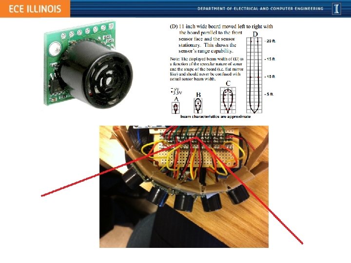
Sensor Detection LV-Max. Sonar-EZ 4 Requirement • Power supply is stable at 5± 0. 1 V • Distance accuracy is within 3 cm. • Field of view is 120 degrees. Verification • Measured by multimeter • Print out distances and compare to the readings from measuring tape • Measured by protractor
673. 5 m. V 69 inch 125. 0 m. V 13 inch
Sensor Code
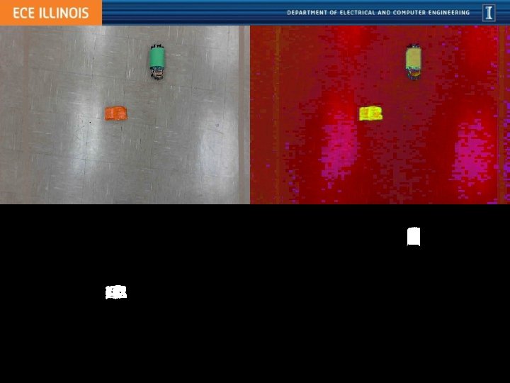
Image Processing Requirement • Power supply is stable at 19 V • Filter out the background and preserve car’s object • Calculate the coordinates and turning direction Verification • Charged from outlet • Print out the picture processed and verify by visual observation • Print out the turning command compare with the actual behavior
Environment • Eclipse • Java • Open. CV
IPC Code
Calculation •
Sample Tests
Total Costs Item Name Unit Cost ($) Quantity Total Cost ($) Logitech c 270 web camera 30 1 30 LV-Maxsensor-EZ 4 30 5 150 Laptop 300 1 300 Toy Cars 30 2 60 Arduino Mega 2560 59 1 59 9 V Battery 5 1 5 XBee 802. 15. 4 25 2 50 Resistors 0. 1 5 0. 5 PNP switches 0. 5 4 2 Total 666. 5
Failures • The view range of the camera is very limited. This is unexpected and not included in the Design Review. • The delay in camera mode is about 0. 3 – 0. 4 s, which is not tolerable in real time chasing. • The sensors are sensitive to any objects. They cannot tell which is the running car. • Due to the delay from the camera mode, we cannot find a proper algorithm for MCU to switch between modes.
Future Works • Find a better camera to solve the view range problem • Carry out a decent algorithm for sensors to separate moving objects and still objects • Object dodging algorithm • Find a way to minimize the delay in camera mode • Implement the mode switching algorithm
Thank you! Professor Carney Mustafa Mukadam Electronic parts shop
Questions?