Automatic Volume Control ECE 445 Team 23 Eric


 B (V 1 > V 3)")


- Slides: 37
Automatic Volume Control ECE 445 Team #23 Eric Davila Roland Le Grand Chris Goulet 4/30/13
Objectives �Build a system which automatically adjusts the volume of your speakers based on how far you are from them �Functions with any bluetooth device and up to three speakers
Original Design �High Level Block Diagram
Original Design �Central Hub Diagram
Original Design �Speaker System Diagram
Original Design �Transmitter Diagram
Main Components �Power Supply �Speakers �Microcontroller �Sensors �Transmitter �Logic Unit
Power Supply �Supply power to all components that don’t have their own power supply- lots of wire will be necessary! �Supply normal voltage levels like 3 V, 5 V, and 12 V DC �Receive power from the wall
Speakers �The automatic sound amplification takes place here after receiving the signal from the microcontroller, then the music is played from the transducer �Amplification will be from a variable op-amp circuit, then that signal will be sent to the actual speakers
Microcontroller �Texas Instruments MSP 430 G 2553 �Low cost � 62. 5 ns instruction time �Easy to set up �Sufficient amount of IO pins
Sensors WT 32 Bluetooth Audio Module From Bluegigga • UART interface with Microcontroller • 3. 3 V power supply
Transmitter �Samsung Galaxy S II �Bluetooth v 3. 0 + HS � 3. 7 Volt, Lithium Ion 1800 m. Ah battery
Logic Unit �Implemented with TTL logic �Inputs = Analog signals from MCUs �Outputs = Binary signal to indicate ON/OFF state �Advantages: �Low cost �Low power consumption �Disadvantages: �Rigid implementation �Number of parts
Design Adjustments �The power supply actually only had to provide 3. 3 V and 5 V DC �Variable op-amp circuit isn’t necessary, a digital potentiometer will take care of volume amplification
Power Supply �Reused an old computer power supply, a Bestec ATX-300 -12 E, with DC outputs: �+12 V , 15 A �+5 V, 30 A �+3. 3 V, 28 A �-12 V, 0. 8 A �+5 VSB, 2 A �Only 3. 3 V, 5 V, and ground outputs were necessary
Power Supply �Issue: Many different connections needed to be made with long wires �Solution: Use wire disconnects for easy connection variability and wire nuts to merge many wires from one
Power Supply �Issue: not functioning properly when disconnected from the computer �Solution: after some research, I learned to connect the VSB line (green) to ground (black) �This caused the supply’s fan to turn and the voltages to read correctly �Issue: when different voltage lines touched, the supply was shorted and stopped working for a while �Solution: make sure that the loose ends are secure
Speakers � 3 GE 2. 0 Multimedia Speakers so that every speaker would be as loud as the others �Removed the original volume control (mechanical potentiometer) using vacuum soldering iron in the electronics shop
Speaker Circuit Ground Wire Speaker #2 Output Adjusted Music from Wiper Speaker #1 Output Power Input Neutral from Music Source Original Music Input
Speaker Setup �The Digital Potentiometer Replaced the Mechanical Potentiometer
Digipot Connections �Important pins: �Pin 1: INC- change wiper �Pin 2: U/D- wiper goes up or down �Pin 3: RH- input from music source �Pin 5: RW- output to speaker circuit
Digipot Testing �The digipot was successfully tested while the microcontroller controlled it �Results: 15 steps of 600Ω, resistance ranges from 100Ω to 9. 1 kΩ
Logic Unit Schematic Decod er Comparato TTL Logic
Logic Unit Schematic Cont…
Output Results A (V 1 > V 2) B (V 1 > V 3) C (V 2 > V 3) b 1 b 0 SPK 1 SPK 2 SPK 3 0 0 0 1 0 1 0 1 1 0 1 0 0 0 1 1 1 0 0 0 1 1 1 0 0 ✓ All outputs are correct
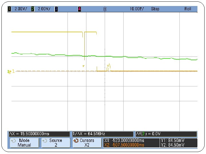
Timing Results
Microcontroller
MSP 430 Pin Layout
MCU Control Loop
Sensors WT 32 Configuration • USB to DB 9 through voltage leveler circuit to Serial UART Shift converter
RSSI to Distance Mapping 100. 00 95. 00 90. 00 85. 00 80. 00 RSSI VALUES 75. 00 Absolute RSSI value avg RSSI Values 70. 00 store 10 (using rsssiavg) 65. 00 60. 00 55. 00 50. 00 0 1 2 3 4 Distance (m) 5 6 7 8
RSSI to Distance Mapping RSSI to Distance Error 6. 00% 5. 00% 4. 00% Absolute error 3. 00% 2. 00% 1. 00% 0. 00% 55 60 65 70 75 Absolute RSSI Value 80 85 90 95
Obstacles �All three of the digital potentiometers burned up from too much current �Rated current: 50μA max, 5 μA standby �Actual current: as much as. 5 V/100Ω = 5000 μA �USB to serial conversion for BT configuration �Garbled messaging over UART between MCU and BT
Future Work �Purchase digipots that can handle much more current �WT 32 has many features to be exploited �Put as many components on a single PCB as possible
Thanks �Igor Federov, our TA �Professor Carney �The Electronics Shop guys: �Mark Smart �Wally Smith �Skot Wiedmann
Questions?