7 Layer OSI Model EECE 542 August 25


 Application Provides Services")
 Application HTTP, FTP, SMTP 6. ) Presentation ASCII, JPEG,")
ll 7. ) (A)pplication (A)way (P)eople 6. ) (P)resentation (P)izza (S)eem 5. )")


 Application PDU Name Data 6. )")


 • Flow control and error detection/correction at the")

 • Logical hierarchical addresses do change when a node")

 • Must reassemble segments into data using sequence numbers")
 • Connection oriented sessions require the sender to first")
 • Sometimes")
 • Provides atomization – Multiple connections can be treated")


 Transport")

 • At the data link layer (layer 2), defines MAC")
- Slides: 34
7 Layer OSI Model EECE 542 August 25, 2003
History • Rapid growth of computer networks caused compatibility problems • ISO recognized the problem and released the OSI model in 1984 • OSI stands for Open Systems Interconnection and consists of 7 Layers • The use of layers is designed to reduce complexity and make standardization easier
7 Layers of the OSI Model Layer Responsible For: 7. ) Application Provides Services to User Apps 6. ) Presentation Data Representation 5. ) Session Communication Between Hosts 4. ) Transport Flow Ctrl, Error Detection/Correction 3. ) Network End to End Delivery, Logical Addr 2. ) Data Link Media Access Ctrl, Physical Addr 1. ) Physical Medium, Interfaces, Puts Bits on Med.
Examples Layer Example 7. ) Application HTTP, FTP, SMTP 6. ) Presentation ASCII, JPEG, PGP 5. ) Session BOOTP, Net. BIOS, DHCP, DNS 4. ) Transport TCP, UDP, SPX 3. ) Network IP, IPX, ICMP 2. ) Data Link Ethernet, Token Ring, Frame Relay 1. ) Physical Bits, Interfaces, Hubs
Mnemonics (A)ll 7. ) (A)pplication (A)way (P)eople 6. ) (P)resentation (P)izza (S)eem 5. ) (S)ession (S)ausage (T)o 4. ) (T)ransport (T)hrow (N)eed 3. ) (N)etwork (N)ot (D)ata 2. ) (D)ata Link (D)o (P)rocessing 1. ) (P)hysical (P)lease
Flat Addressing • Flat addressing schemes do not provide anything other than a unique identifier. They provide no real information about where the object being addressed resides. • Example: SSN# (may provide insight to where the person was born, but not to where they are now)
Hierarchical Addressing • Hierarchical addressing schemes provide layers or a hierarchy to the address that provide information about where the addressed object exists within the hierarchy. • Example: phone numbers (area code, local prefix, and four digit number unique to that area code/prefix combination).
Talking to Everyone • Special kinds of addresses exist at both layer #2 and #3 called broadcast addresses • Typically network devices are interested in only traffic addressed directly for them and any traffic addressed with the destination address set to broadcast • If they are paying attention to other traffic, they are said to be in promiscuous mode
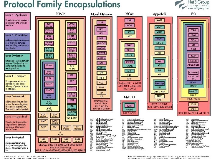
Encapsulation • Data exists at each layer contained within a unit called a Protocol Data Unit (PDU). • PDU’s are referred two ways: N-PDU, and by special names. • The process by which data moves between PDU types is called Encapsulation • PDU move through interfaces between layers using Service Access Points (SAP)
PDU’s And the OSI Model Layer 7. ) Application PDU Name Data 6. ) Presentation Data 5. ) Session Data 4. ) Transport Segment 3. ) Network Packet 2. ) Data Link Frame 1. ) Physical Bits
Layer 1: The Physical Layer • Defines physical medium and interfaces • Determines how bits are represented • Controls transmission rate & bit synchronization • Controls transmission mode: simplex, halfduplex, & full duplex • PDU: Bits • Devices: hubs, cables, connectors, etc…
Layer 2: The Data Link Layer • PDU: Frames • Keeps Link alive & provides connection for upper layer protocols • Based on physical (flat) address space • Physical addresses are fixed and don’t change when the node is moved • Medium/media access control
The Data Link Layer (cont. ) • Flow control and error detection/correction at the frame level. Think collisions… • Topology • Ex: Ethernet, Token Ring, ISDN • Sublayers: MAC (framing, addressing, & MAC) & LLC (logical link control – gives error control & flow control) • Devices: switches, bridges, NIC’s
Layer 3: The Network Layer • • • PDU: Packet End to end delivery of packets Creates logical paths Path determination (routing) Hides the lower layers making things hardware independent • Uses logical hierarchical addresses
The Network Layer (cont. ) • Logical hierarchical addresses do change when a node is moved to a new subnet • Devices: routers, firewalls
Layer 4: The Transport Layer • PDU: Segment • Service Point Address (more often called a port) used to track multiple sessions between the same systems. SPA’s are used to allow a node to offer more than one service (i. e. it could offer both mail and web services) • This layer is why you have to specify TCP or UDP when dealing with TCP/IP
The Transport Layer (cont. ) • Must reassemble segments into data using sequence numbers • Can use either connectionless or connection oriented sessions • Connectionless sessions rely on upper layer protocols for error control and are often used for faster less reliable links • Ex: UDP (used by things like NFS & DNS)
The Transport Layer (cont. ) • Connection oriented sessions require the sender to first request a connection, the receiver to acknowledge the connection, and that they negotiate how much data can be sent/received before its reception is acknowledged • Uses acknowledgements & retransmission for error correction • Example: TCP (used by things like telnet, http)
Layer 5: The Session Layer • PDU: Data (from here on up) • Sometimes called the dialog controller, this layer establishes, maintains, and terminates sessions between applications • Sets duplex between applications • Defines checkpoints for acknowledgements during sessions between applications
The Session Layer (cont. ) • Provides atomization – Multiple connections can be treated as one virtual session. If one fails or is terminated, all should be terminated. • Identifies raw data as either application data or session control information • Uses fields provided by layers 3 & 4 to track dialogs between applications / services • Provides translations for naming services • Ex: RPC, X-Windows, LDAP, NFS
Layer 6: The Presentation Layer • Data formatting, translation, encryption, and compression • Ex: ASCII, EBCDIC, HTML, JPEG
Layer 7: The Application Layer • Provides communication services to applications • Ex: HTTP, FTP, SMTP
Encapsulation Review Example of the encapsulation / decapsulation process
Address Resolution • Two problems: • #1 Layer 3 address resolution • #2 Layer 3 to Layer 2 resolution • IP vs IPX approaches
Larger Example • Scenario: sending a message between subnets. • Source and Destination Layer 3 addresses don’t change • Source and Destination Layer 2 addresses do • How are addresses resolved?
The Practical Benefits Of Understanding The OSI Model • Helps with packet analysis • Helps foresee problems • Aides in network design (especially on large scale networks)
Network Design & Admin Issues • Examining network protocols and how they relate to the OSI model help aide network administers design networks and help admins troubleshoot strange behavior. • If you don’t understand what mechanisms your network is using to communicate, you are more likely to introduce new problems while trying to fix old ones.
Example #1 • Admin wants to play around with DHCP so they put the machines that they want to use on “private IP addresses”. • What will happen to “normal” DHCP users?
Example #2 • Network congestion: Admin notices that he is seeing to much traffic on his network. He decides to break his network in two using a router. • What are some potential problems associated with this? • What might be some better solutions?
TCP/IP Model • Much older than OSI model • Consists of 4 layers instead of 7 • TCP/IP model can be mapped to the OSI model
TCP/IP vs OSI TCP/IP Application Transport OSI Application Presentation Session (Layers 7 -5) Transport (Layer 4) Internet Network (Layer 3) Network Interface Data Link Physical (Layers 1 -2)
IEEE Standards • IEEE project 802 started in 1985 • Adopted by ANSI in 1987 • Recognized as an international standard by the ISO as ISO 8802 • Deals with layers 1 & 2
IEEE Standards (cont. ) • At the data link layer (layer 2), defines MAC and LLC sublayers • LLC covers media independent topics (802. 2 is the LLC standard) • MAC topics are dependent on media (802. 3, 802. 11, 802. 5) • At the physical layer (layer 1), defines a PMI and PMD