12 PLATE HEAT EXCHANGERS 12 1 Gasketed plate


- Slides: 23
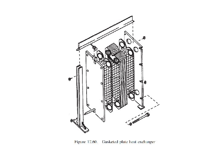
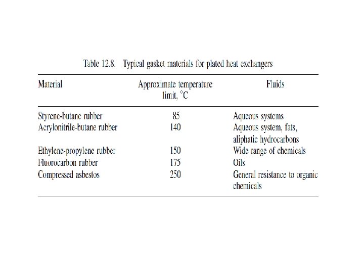
12. PLATE HEAT EXCHANGERS 12. 1. Gasketed plate heat exchangers A gasketed plate heat exchanger consists of a stack of closely spaced thin plates clamped together in a frame. A thin gasket seals the plates round their edges. The plates are normally between 0. 5 and 3 mm thick and the gap between them 1. 5 to 5 mm. Plate surface areas range from 0. 03 to 1. 5 m 2, with a plate width: length ratio from 2. 0 to 3. 0. The size of plate heat exchangers can vary from very small, 0. 03 m 2, to very large, 1500 m 2. The maximum flow-rate of fluid is limited to around 2500 m 3/h. The basic layout and flow arrangement for a gasketed plate heat exchanger is shown in Figure 12. 60. Corner ports in the plates direct the flow from plate to plate. The plates are embossed with a pattern of ridges, which increase the rigidity of the plate and improve the heat transfer performance. Plates are available in a wide range of metals and alloys; including stainless steel, aluminium and titanium. A variety of gasket materials is also used; see Table 12. 8.
Selection The advantages and disadvantages of plate heat exchangers, compared with conventional shell and tube exchangers are listed below: Advantages 1. Plates are attractive when material costs are high. 2. Plate heat exchangers are easier to maintain. 3. Low approach temps can be used, as low as 1 ŽC, compared with 5 to 10 ŽC for shell and tube exchangers. 4. Plate heat exchangers are more flexible, it is easy to add extra plates. 5. Plate heat exchangers are more suitable for highly viscous materials. 6. The temperature correction factor, Ft, will normally be higher with plate heat exchangers, as the flow is closer to true countercurrent flow. 7. Fouling tends to be significantly less in plate heat exchangers; see Table 12. 9.
Disadvantages 1. A plate is not a good shape to resist pressure and plate heat exchangers are not suitable for pressures greater than about 30 bar. 2. The selection of a suitable gasket is critical; see Table 12. 8. 3. The maximum operating temperature is limited to about 250 ŽC, due to the performance of the available gasket materials. Plate heat exchangers are used extensively in the food and beverage industries, as they can be readily taken apart for cleaning and inspection. Their use in the chemical industry will depend on the relative cost for the particular application compared with a conventional shell and tube exchanger; see Parker (1964) and Trom (1990).
Plate heat exchanger design It is not possible to give exact design methods for plate heat exchangers. They are proprietary designs, and will normally be specified in consultation with the manufacturers. Information on the performance of the various patterns of plate used is not generally available.
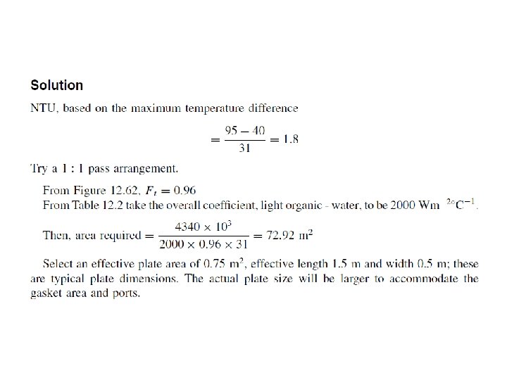
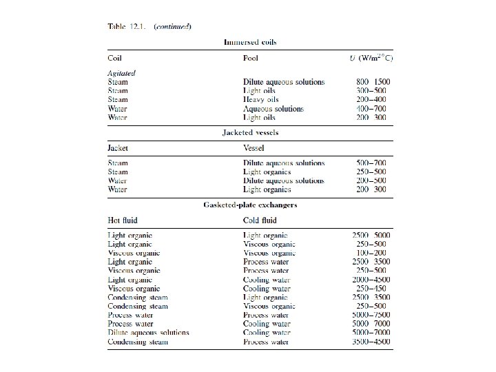
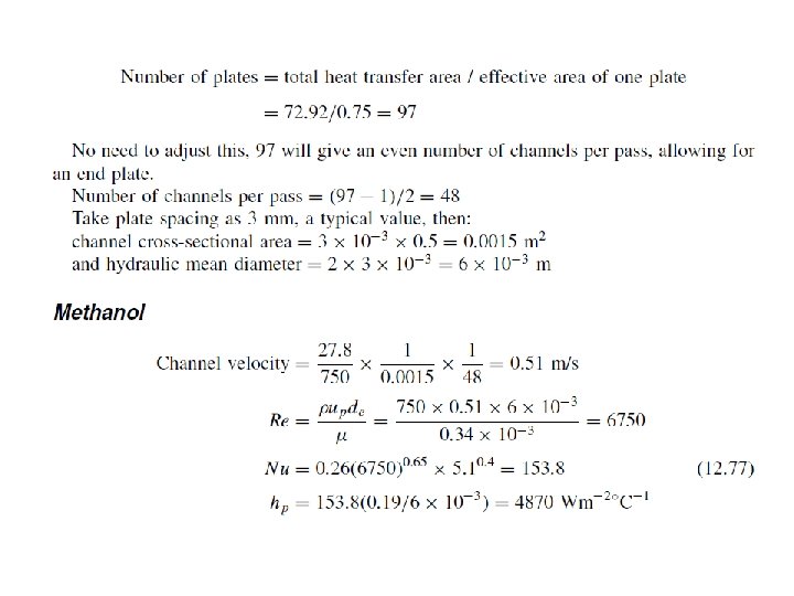
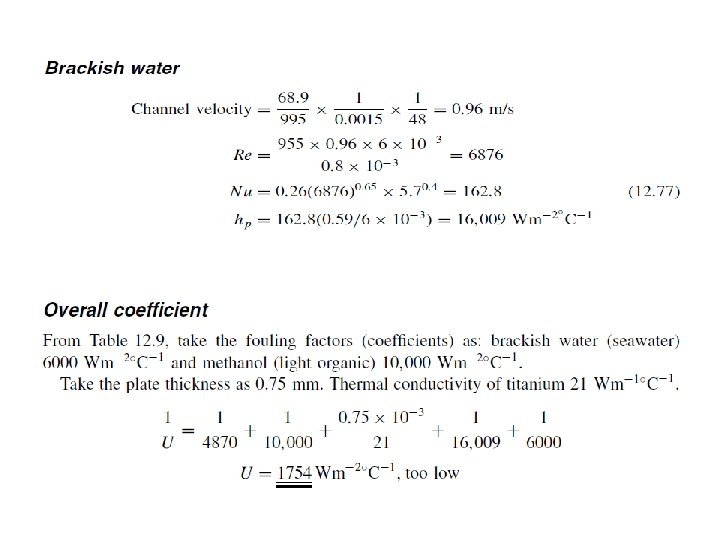
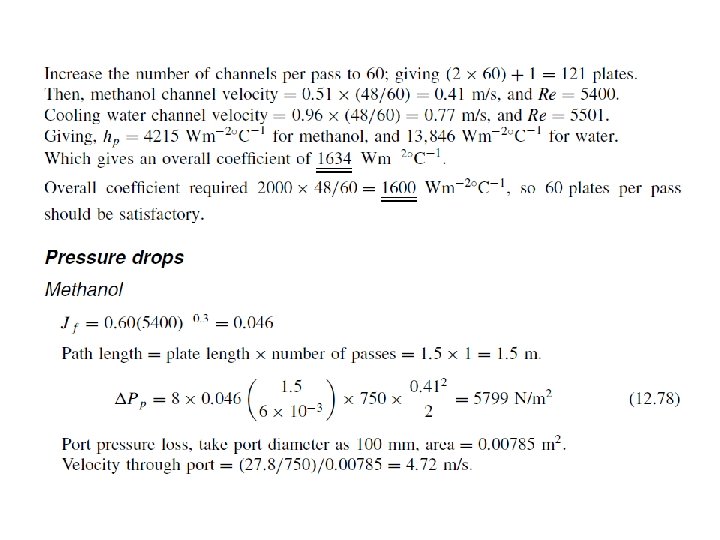
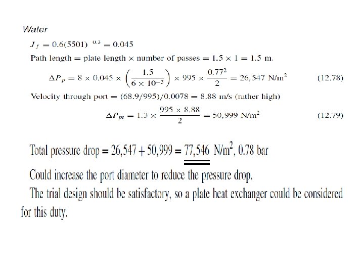
Procedure The design procedure is similar to that for shell and tube exchangers. 1. Calculate duty, the rate of heat transfer required. 2. If the specification is incomplete, determine the unknown fluid temperature or fluid flow-rate from a heat balance. 3. Calculate the log mean temperature difference, �TLM. 4. Determine the log mean temperature correction factor, Ft; see method given below. 5. Calculate the corrected mean temperature difference �Tm D Ft ð �TLM. 6. Estimate the overall heat transfer coefficient; see Table 12. 1. 7. Calculate the surface area required; equation 12. 1. 8. Determine the number of plates required D total surface area/area of one plate. 9. Decide the flow arrangement and number of passes. 10. Calculate the film heat transfer coefficients for each stream; see method given below. 11. Calculate the overall coefficient, allowing for fouling factors. 12. Compare the calculated with the assumed overall coefficient. If satisfactory, say 0% to C 10% error, proceed. If unsatisfactory return to step 8 and increase or decrease the number of plates. 13. Check the pressure drop for each stream; see method given below. This design procedure is illustrated in Example 12. 13.
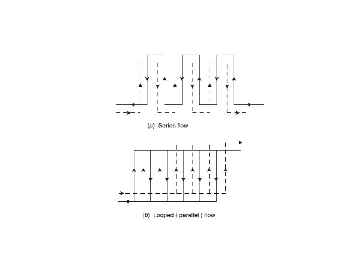
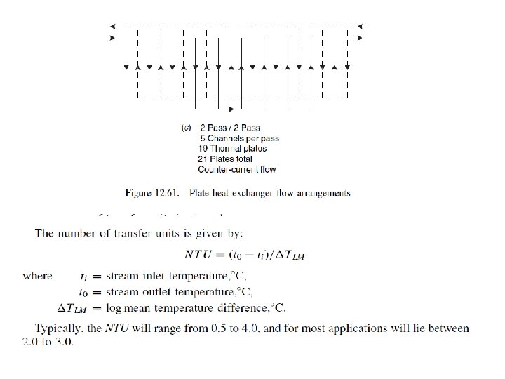
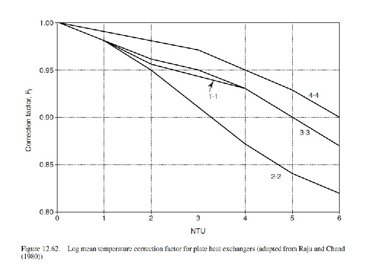
Flow arrangements The stream flows can be arranged in series or parallel, or a combination of series and parallel, see Figure 12. 61. Each stream can be sub-divided into a number of passes; analogous to the passes used in shell and tube exchangers. Estimation of the temperature correction factor For plate heat exchangers it is convenient to express the log mean temperature difference correction factor, Ft, as a function of the number of transfer units, NTU, and the flow arrangement (number of passes); see Figure 12. 62. The correction will normally be higher for a plate heat exchanger than for a shell and tube exchanger operating with the same temperatures. For rough sizing purposes, the factor can be taken as 0. 95 for series flow.
Heat transfer coefficient The equation forced-convective heat transfer in conduits can be used for plate heat exchangers; equation 12. 10. The values for the constant C and the indices a, b, c will depend on the particular type of plate being used. Typical values for turbulent flow are given in the equation below,
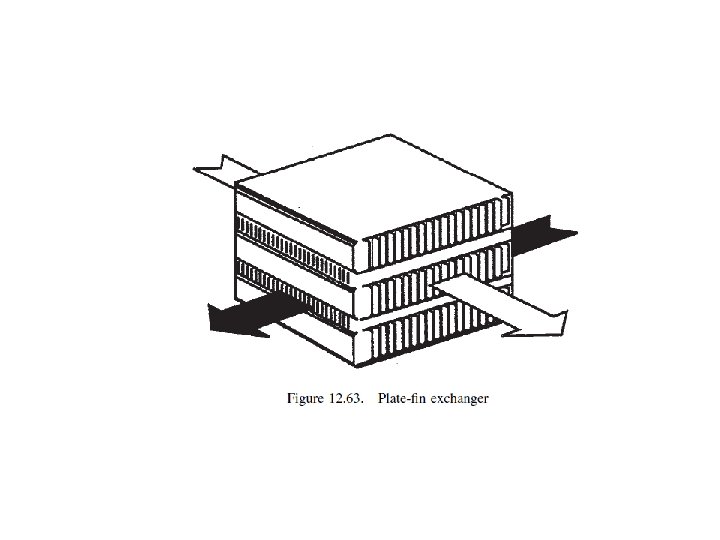
12. 2. Welded plate heat exchangers use plates similar to those in gasketed plate exchangers but the plate edges are sealed by welding. This increases the pressure and temperature rating to up to 80 bar and temperatures in excess of 500 C. 12. 3. Plate-fin exchangers consist essentially of plates separated by corrugated sheets, which form the fins. They are made up in a block and are often referred to as matrix exchangers; see Figure 12. 63. They are usually constructed of aluminium and joined and sealed by brazing. The main application of plate-fin exchangers has been in the cryogenics industries, such as air separation plants, where large heat transfer surface areas are needed. They are now finding wider applications in the chemical processes industry, where large surface area, compact, exchangers are required.