1 FEL Offset Mirrors LCLS Week FAC Meeting
- Slides: 16
1 FEL Offset Mirrors LCLS Week * FAC Meeting 26– 27 October 2005 26 -27 OCT 2005 UCRL-PRES-216326 Michael Pivovaroff pivovaroff 1@llnl. gov
2 Overview FEL offset mirrors will serve as a low-pass filter, eliminating the high-energy spontaneous spectrum Basic concept is to rely on the relatively sharp, step-function nature of grazingincidence reflectivity curves Original plan calls for two sets of mirrors Be: Si. C: 26 -27 OCT 2005 operates below 2 ke. V @13 mrad operates above 2 ke. V @1. 5 mrad UCRL-PRES-216326 Michael Pivovaroff pivovaroff 1@llnl. gov
3 Approach Actual implementation must account for: Safety Cost Complexity Guided by ISM Core Functions Define work scope Analyze work for hazards (e. g. , use of beryllium) Must start with physics requirements 26 -27 OCT 2005 UCRL-PRES-216326 Michael Pivovaroff pivovaroff 1@llnl. gov
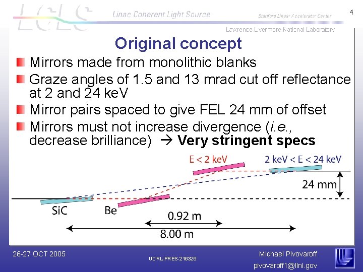
4 Original concept Mirrors made from monolithic blanks Graze angles of 1. 5 and 13 mrad cut off reflectance at 2 and 24 ke. V Mirror pairs spaced to give FEL 24 mm of offset Mirrors must not increase divergence (i. e. , decrease brilliance) Very stringent specs 26 -27 OCT 2005 UCRL-PRES-216326 Michael Pivovaroff pivovaroff 1@llnl. gov
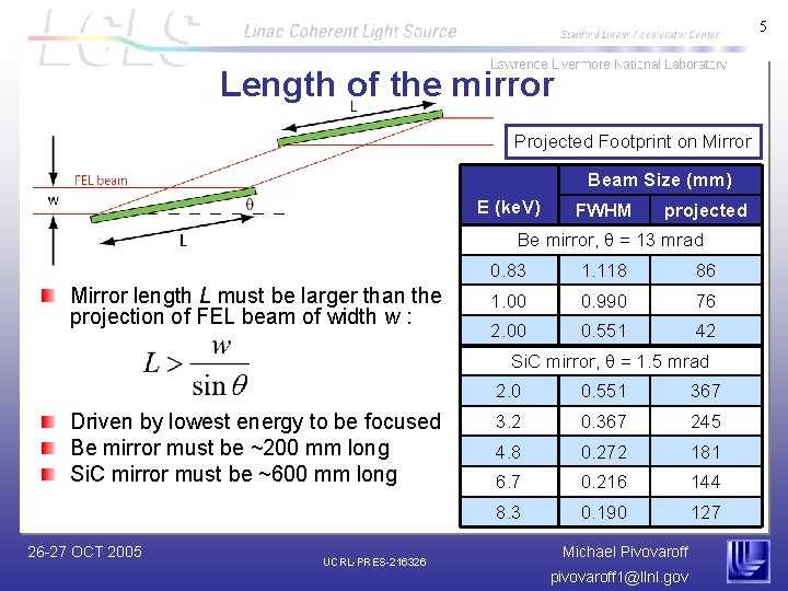
5 Length of the mirror Projected Footprint on Mirror Beam Size (mm) E (ke. V) FWHM projected Be mirror, q = 13 mrad Mirror length L must be larger than the projection of FEL beam of width w : 0. 83 1. 118 86 1. 00 0. 990 76 2. 00 0. 551 42 Si. C mirror, q = 1. 5 mrad Driven by lowest energy to be focused Be mirror must be ~200 mm long Si. C mirror must be ~600 mm long 26 -27 OCT 2005 UCRL-PRES-216326 2. 0 0. 551 367 3. 2 0. 367 245 4. 8 0. 272 181 6. 7 0. 216 144 8. 3 0. 190 127 Michael Pivovaroff pivovaroff 1@llnl. gov
6 General approach to mirror specifications Need to worry about three regimes: Low-spatial frequency (i. e. , figure): Length scales > 1 mm High-spatial frequency (i. e. , finish) Length scales < 1 micron Mid-spatial frequency (typically called “mids”) 1 micron < length scales < 1 mm Overall goal is to increase divergence less than 10% 26 -27 OCT 2005 UCRL-PRES-216326 Michael Pivovaroff pivovaroff 1@llnl. gov
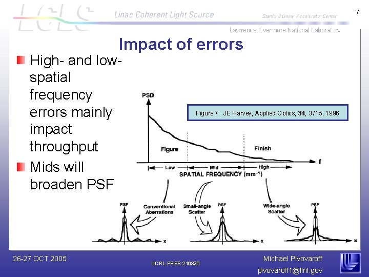
7 Impact of errors High- and lowspatial frequency errors mainly impact throughput Mids will broaden PSF 26 -27 OCT 2005 Figure 7: JE Harvey, Applied Optics, 34, 3715, 1996 UCRL-PRES-216326 Michael Pivovaroff pivovaroff 1@llnl. gov
8 Figure specifications Mirrors should not increase divergence more than 10% At 8 ke. V, divergence Ds= 1 mrad Two independent reflections, Dsmirror ≤ 71 nrad (0. 015″) 7. 1 nm PV over 100 mm Very challenging! 600 mm long CVD-Si. C mirror made for ESRF had slope error of 3 μrad (0. 3″) 26 -27 OCT 2005 UCRL-PRES-216326 Michael Pivovaroff pivovaroff 1@llnl. gov
9 Mids specifications Past experience with grazing incidence optics indicates mids are often the limiting factor in performance. Specs will be determined through analytic methods and Monte Carlo simulations. 26 -27 OCT 2005 UCRL-PRES-216326 Michael Pivovaroff pivovaroff 1@llnl. gov
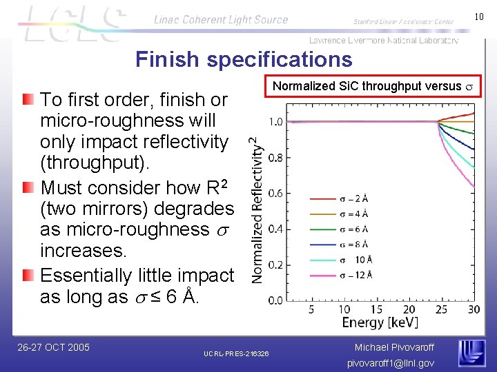
10 Finish specifications To first order, finish or micro-roughness will only impact reflectivity (throughput). Must consider how R 2 (two mirrors) degrades as micro-roughness s increases. Essentially little impact as long as s ≤ 6 Å. 26 -27 OCT 2005 UCRL-PRES-216326 Normalized Si. C throughput versus s Michael Pivovaroff pivovaroff 1@llnl. gov
11 Concerns with current baseline plan Material choices: Use of beryllium requires additional safety measures Be is incredibly difficult to polish Current work indicates best finish achievable is the range s = 15 – 25 Å Fabrication method: Monolithic mirrors are very expensive State-of-the-art mirrors may not even meet spec Is there another approach that can reduce cost and risk? 26 -27 OCT 2005 UCRL-PRES-216326 Michael Pivovaroff pivovaroff 1@llnl. gov
12 Thin coatings on silicon substrates Deposit Si. C and B 4 C (instead of Be) on super-polished, figured Si substrates Advantages Lower cost Eliminates beryllium-related safety issues Leverages expertise and infrastructure developed at LLNL for the EUVL project Si. C and B 4 C properties currently being optimized for their use in multilayer applications for LCLS 26 -27 OCT 2005 UCRL-PRES-216326 Michael Pivovaroff pivovaroff 1@llnl. gov
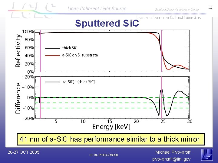
13 Sputtered Si. C 41 nm of a-Si. C has performance similar to a thick mirror 26 -27 OCT 2005 UCRL-PRES-216326 Michael Pivovaroff pivovaroff 1@llnl. gov
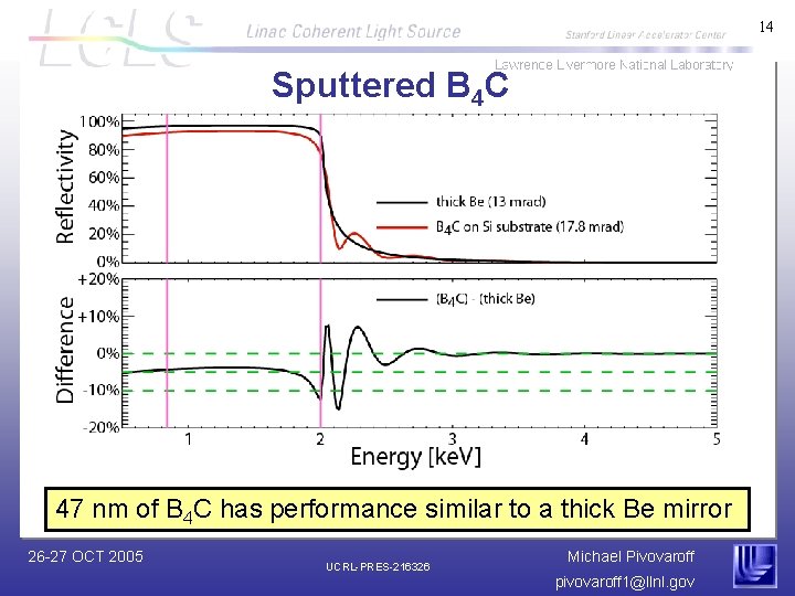
14 Sputtered B 4 C 47 nm of B 4 C has performance similar to a thick Be mirror 26 -27 OCT 2005 UCRL-PRES-216326 Michael Pivovaroff pivovaroff 1@llnl. gov
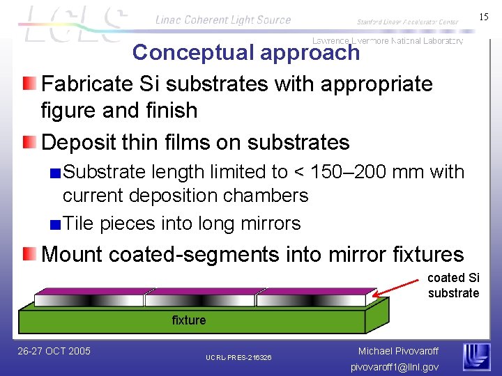
15 Conceptual approach Fabricate Si substrates with appropriate figure and finish Deposit thin films on substrates Substrate length limited to < 150– 200 mm with current deposition chambers Tile pieces into long mirrors Mount coated-segments into mirror fixtures coated Si substrate fixture 26 -27 OCT 2005 UCRL-PRES-216326 Michael Pivovaroff pivovaroff 1@llnl. gov
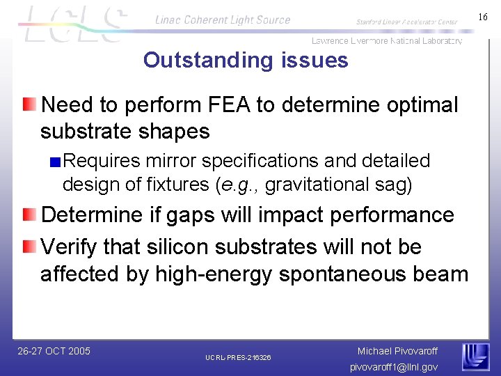
16 Outstanding issues Need to perform FEA to determine optimal substrate shapes Requires mirror specifications and detailed design of fixtures (e. g. , gravitational sag) Determine if gaps will impact performance Verify that silicon substrates will not be affected by high-energy spontaneous beam 26 -27 OCT 2005 UCRL-PRES-216326 Michael Pivovaroff pivovaroff 1@llnl. gov