1 Decoders 2 Encoders 3 Multiplexers 4 Demultiplexers
 2. 엔코더(Encoders) 3. 멀티플렉서(Multiplexers) 4. 디멀티플렉서(Demultiplexers) 5. 크기 비교기(Magnitude Comparators) 6.")
 • 단일 게이트(AND/NAND)와 몇 몇 Inverter 를 사용한다. • Example: 4")
 Figure 5. 1 109")

 2. Set")
 117")

 120")
 121")
 122")
 – Pop-up menu 123")

 Figure 5. 21 125")


 • WITH SELECT 의 VHDL Architecture 구 문을 사용한다.")


 : 일부 ** EQUATIONS ** d 0 : INPUT; d")

 I • Seven Segment signal declarations ARCHITECTURE seven_segment OF bcd_7")
 II • SS Architecture는 몇 몇 상태가 필요하다. WITH input")
 III • SS Architecture(계속) a <= output(6); b <= output(5);")


 PROCESS(n.")


 • A WHEN ELSE is similar to If-Then-Else. ENTITY hi_pri 8")
 • If-Then-Else문은 반드시 PROCESS문 내에만 사용된다. ENTITY hi_pri 8 a IS")
 Y = D 0!S 1!S")
 ARCHITECTURE mux 4 to 1 OF mux 4 case IS")
;")

 -- compare 2. vhd (It is difficult to type")
 LIBRARY ieee; USE ieee. std_logic_1164. ALL; ENTITY compare 4")
 PROCESS (a, b) -- Sensitive to A and B")


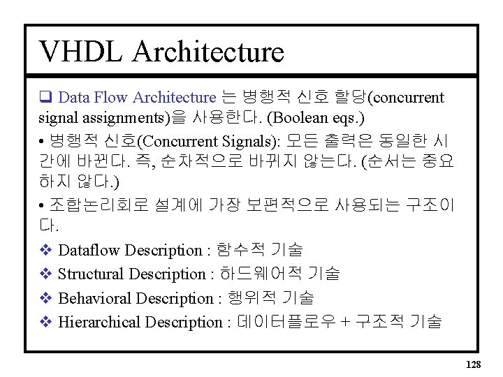
- Slides: 88
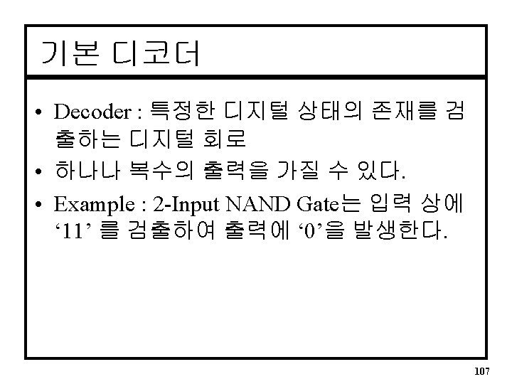
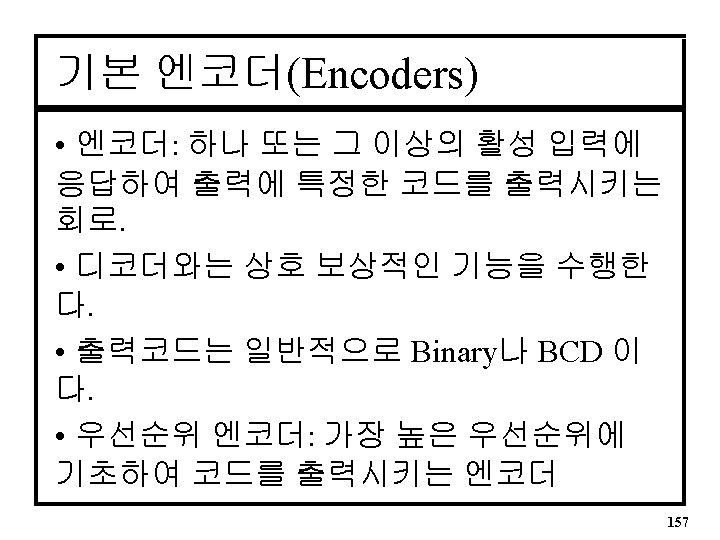
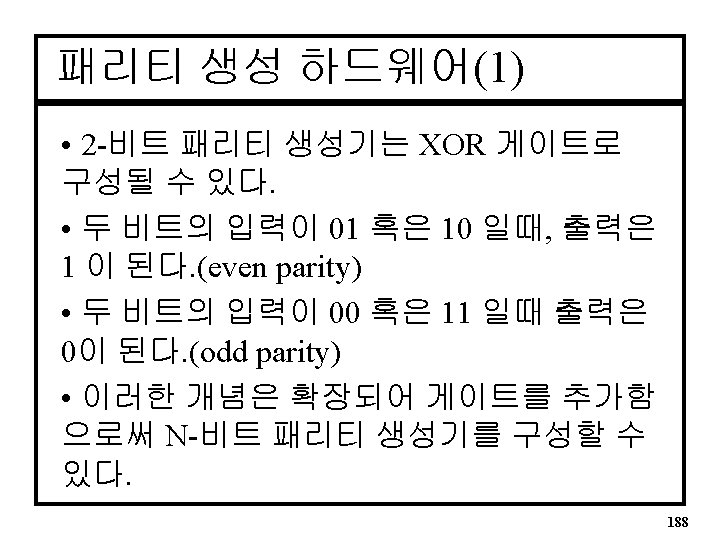
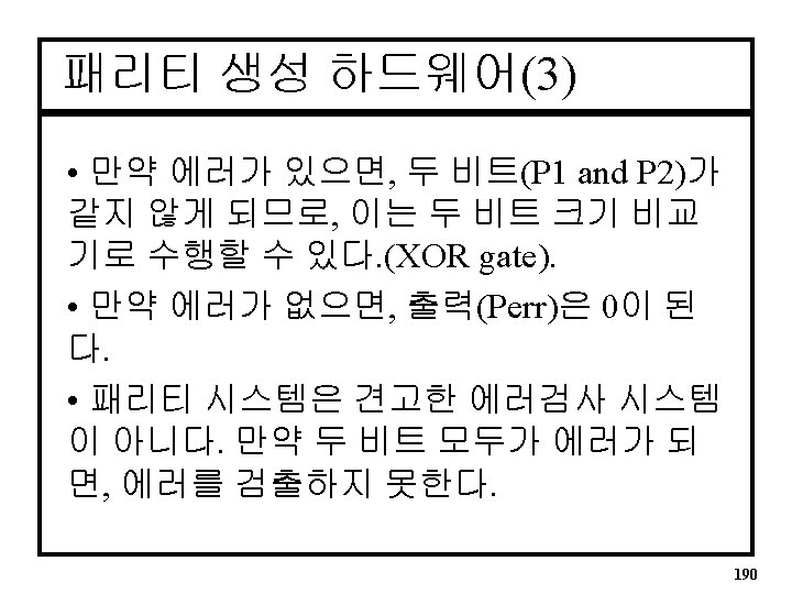
단원목차 1. 디코더(Decoders) 2. 엔코더(Encoders) 3. 멀티플렉서(Multiplexers) 4. 디멀티플렉서(Demultiplexers) 5. 크기 비교기(Magnitude Comparators) 6. 패리티 생성기 및 검사기(Parity Generators and Checkers) 106
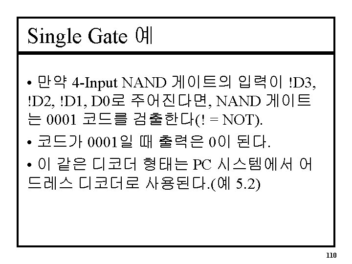
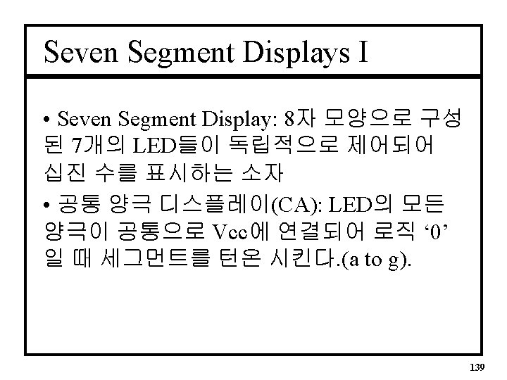
Single Gate 디코더(1) • 단일 게이트(AND/NAND)와 몇 몇 Inverter 를 사용한다. • Example: 4 -Input AND는 입력에 ‘ 1111’를 검출하여 출력에 ‘ 1’을 발생시킨다. • 입력은 D 3, D 2, D 1, D 0로 표기되고, D 3는 MSB(most significant bit), D 0는 LSB (least significant bit)가 된다. • See Figure 5. 1 108
Single Gate 디코더(2) Figure 5. 1 109
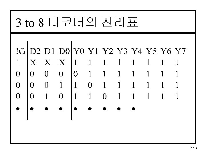
3 to 8 디코더 회로 Figure 5. 6 113
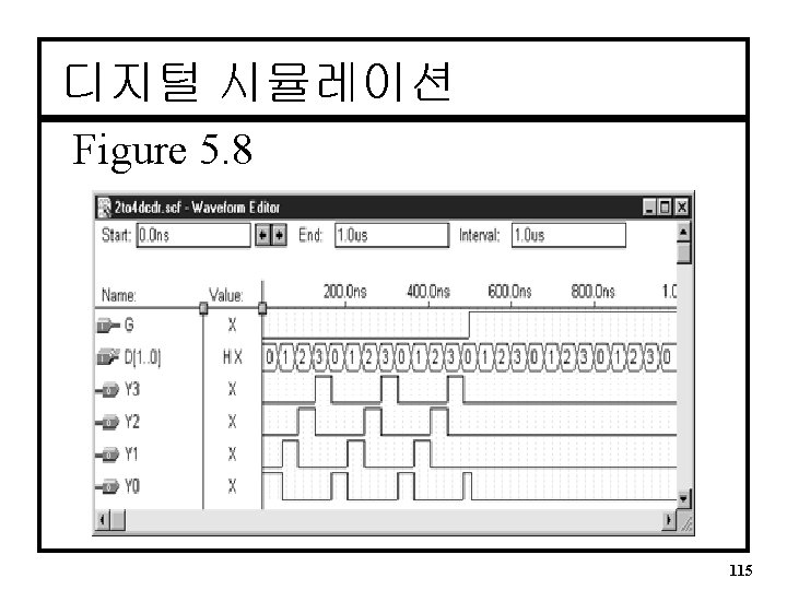
MAX+PLUSII 시뮬레이션 q 기본과정 1. Enter Nodes from SNF (on Node Menu) 2. Set End Time (File Menu) for length (default = 1. 0 us) 3. Set Grid Size (Options Menu) : 시뮬레이션 시 최 소시간을 결정 • Fig. 5. 9 ~ 5. 15 참조 4. Use Toolbar to set input stimulus 5. Open Simulator Engine, Press Start 116
Enter Nodes from SNF (on Node Menu) 117
Nodes의 선택 118
Setting the End Time (on File Menu) 120
Setting the Grid Size (on Option Menu) 121
Making a Group of signals (1) 122
Making a Group of signals (2) – Pop-up menu 123
Overwrite Count Value 124
시뮬레이션 결과(open. scf file) Figure 5. 21 125
2 to 4 디코더의 VHDL Entity --Basic VHDL Entity for I/O ENTITY decode 1 IS PORT(D 1, D 0 : IN BIT; Y 0, Y 1, Y 2, Y 3 : OUT BIT); END decode 1; v 만약 입력과 출력포트가 std_logic type가 아닌 bit type으로 선언되면 IEEE library 구문이 필요 없다. 126
2 to 4 디코더의 VHDL Architecture -- Use Concurrent Signal Assignment ARCHITECTURE decoder OF decode 1 IS BEGIN Y 0 <= (not D 1) and (not D 0); Y 1 <= (not D 1) and (D 0); Y 2 <= (D 1) and (not D 0); Y 3 <= (D 1) and (D 0); END decoder; 127
선택적 신호 할당(Selected Signal Assignments) • WITH SELECT 의 VHDL Architecture 구 문을 사용한다. • 기본형식: –WITH (signal input(s)) SELECT –signal input states are used to define the output state changes. 129
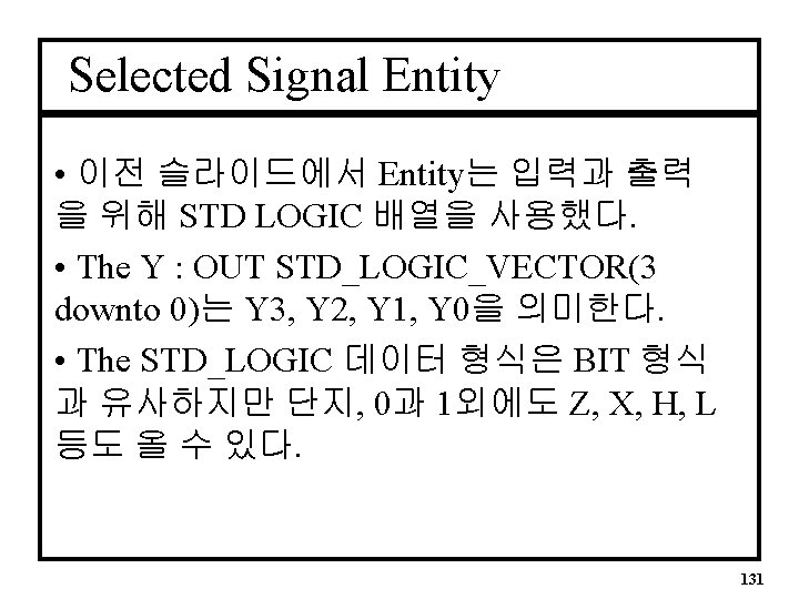
디코더의 VHDL Entity • Basic Entity for Selected Signal ENTITY decode 1 IS PORT( D Y : IN STD_LOGIC_VECTOR(1 downto 0); : OUT STD_LOGIC_VECTOR(3 downto 0)); END decode 1; 130
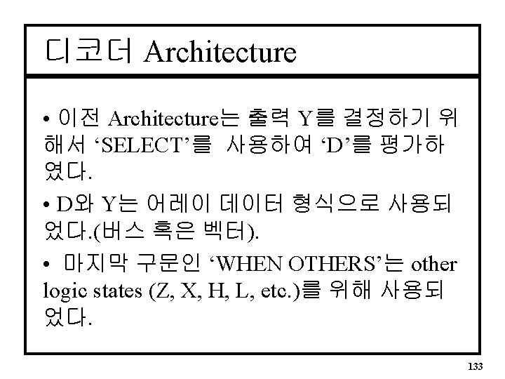
Selected Signal Architecture • Basic Architecture ARCHITECTURE decoder OF decode 1 IS BEGIN WITH D SELECT Y <= “ 0001” WHEN “ 00”, “ 0010” WHEN “ 01”, “ 0100” WHEN “ 10”, “ 1000” WHEN “ 11”, “ 0000” WHEN OTHERS; END decoder; 132
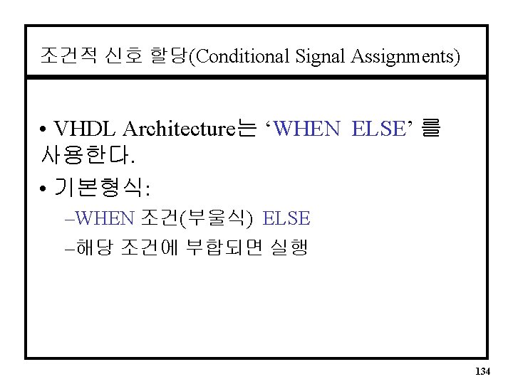
Conditional Signal Architecture • Basic Architecture ARCHITECTURE decoder OF decode 1 IS BEGIN Y <= “ 0001” WHEN D = “ 00” ELSE 순차적으로 평가 (서로 종속적) “ 0010” WHEN D = “ 01” ELSE “ 0100” WHEN D = “ 10” ELSE “ 1000” WHEN D = “ 11” ELSE “ 0000” ; END decoder; Altera는 CPLD 내부회로의 효율성을 위해 “conditional signal assignment” 보다 “selected signal assignment”를 사용하기를 권한다. (Golden Rules) 135
Enable 입력을 갖는 디코더 LIBRARY ieee; USE ieee. std_logic_1164. ALL; ENTITY decode 3 a IS PORT( d : IN STD_LOGIC_VECTOR (1 downto 0); g : IN STD_LOGIC; y : OUT STD_LOGIC_VECTOR (3 downto 0)); END decode 3 a; ARCHITECTURE decoder OF decode 3 a IS SIGNAL inputs : STD_LOGIC_VECTOR (2 downto 0); BEGIN inputs(2) <= g; inputs (1 downto 0) <= d; WITH inputs SELECT y <= "0001" WHEN "000", "0010" WHEN "001", "0100" WHEN "010", "1000" WHEN "011", "0000" WHEN others; END decoder; 136
정수형을 갖는 디코더 LIBRARY ieee; USE ieee. std_logic_1164. all; ENTITY decode 4 g IS PORT( d : IN INTEGER Range 0 to 3; g : IN STD_LOGIC; y : OUT STD_LOGIC_VECTOR (0 to 3)); END decode 4 g; ARCHITECTURE a OF decode 4 g IS BEGIN y <= "1000" WHEN (d=0 and g='0') ELSE "0100" WHEN (d=1 and g='0') ELSE "0010" WHEN (d=2 and g='0') ELSE "0001" WHEN (d=3 and g='0') ELSE "0000"; END a; 137
Report File (. rpt) : 일부 ** EQUATIONS ** d 0 : INPUT; d 1 : INPUT; g : INPUT; -- Node name is 'y 0' -- Equation name is 'y 0', location is LC 118, type is output. y 0 = LCELL( _EQ 001 $ GND); _EQ 001 = !d 0 & !d 1 & !g; -- Node name is 'y 1' -- Equation name is 'y 1', location is LC 115, type is output. y 1 = LCELL( _EQ 002 $ GND); _EQ 002 = d 0 & !d 1 & !g; - 계속 - ! = NOT & = AND # = OR $ = XOR 138
SS Decoder Entity • Basic Entity ENTITY bcd_7 seg IS PORT( d 3, d 2, d 1, d 0 a, b, c, d, e, f, g : IN BIT; : OUT BIT); END bcd_7 seg; -- Defines binary inputs d 0 to d 3 -- Defines SS outputs a to g 143
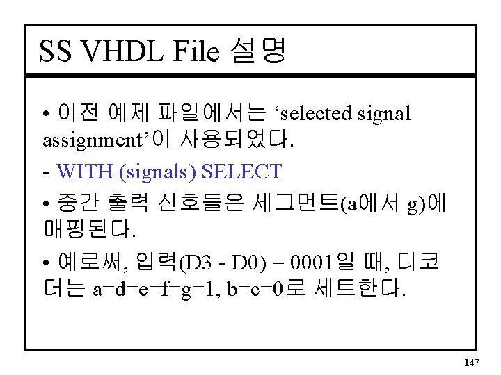
SS VHDL Architecture (CA) I • Seven Segment signal declarations ARCHITECTURE seven_segment OF bcd_7 seg IS SIGNAL input : BIT_VECTOR(3 downto 0); SIGNAL output : BIT_VECTOR(6 downto 0); BEGIN input <= D 3 & D 2 & D 1 &D 0 -- Uses two intermediate signals called input and output -- Creates an array by using the concatenate operator (&) -- In this case input(3) <= D 3, input(2) <= D 2 etc. 144
SS VHDL Architecture (CA) II • SS Architecture는 몇 몇 상태가 필요하다. WITH input SELECT output <= “ 0000001” WHEN “ 0000”, output <= “ 1001111” WHEN “ 0001”, output <= “ 0010010” WHEN “ 0010”, output <= “ 0000110” WHEN “ 0011”, output <= “ 1001100” WHEN “ 0100”, output <= “ 0100100” WHEN “ 0101”, | | | output <= “ 1111111” WHEN OTHERS; 145
SS VHDL Architecture (CA) III • SS Architecture(계속) a <= output(6); b <= output(5); c <= output(4); d <= output(3); e <= output(2); f <= output(1); g <= output(0); END seven_segment; 146
VHDL에서의 Sequential Process • A VHDL Process 는 sequential statements 를 포함함으로 구성된다. sequential statements 는 sensitivity list 상의 신호에 변 화가 있을 때 실행된다. • 기본형식 PROCESS(Sensitivity List) BEGIN Sequential Statements; END PROCESS; 150
CASE Statement Template CASE __expression IS WHEN __constant_value => __statement; WHEN OTHERS => __statement; END CASE; => 여러 값에 따라 결정할 때 Process 문 내에 사용 151
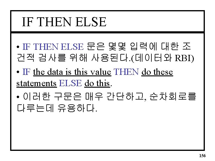
IF Statement Template IF __expression THEN __statement; ELSE __statement; END IF; => TRUE or FALSE 조건에 따라 결정할 때 Process 문 내에 사용 152
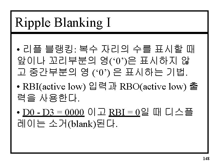
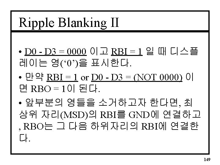
Ripple Blanking Process구문 I • 이전 파일에 기본 프로세스 구문이 더해진다. (sevsegrb. vhd) PROCESS(n. RBI, input) BEGIN IF(input = “ 0000” and n. RBI = ‘ 0’) THEN output <= “ 1111111”; -- Suppressed 0 n. RBO <= ‘ 0’; ELSIF(input = “ 0000” and n. RBI = ‘ 1’) THEN output <= “ 0000001”; -- Display a 0 n. RBO <= ‘ 1’; ELSE -- Continued on next slide 153
Ripple Blanking Process구문 II • 이전 파일의 일부를 변경 CASE input IS WHEN “ 0001” => output <= “ 1001111”; -- a 1 Displayed WHEN “ 0010” => output <= “ 0010010”; -- a 2 Displayed | | | WHEN Others => output <= “ 1111111”; -- Blank END CASE; n. RBO <= ‘ 1’; END IF; 154
CASE 문 • SS 디스플레이를 위한 출력을 발생시키기 위해 리플 블랭킹 설계에서 선택적 신호 할 당문(With Select)을 Case문으로 교체 했다. • The Process Steps are evaluated in sequence first the IF statements, then the Case and so on. 155
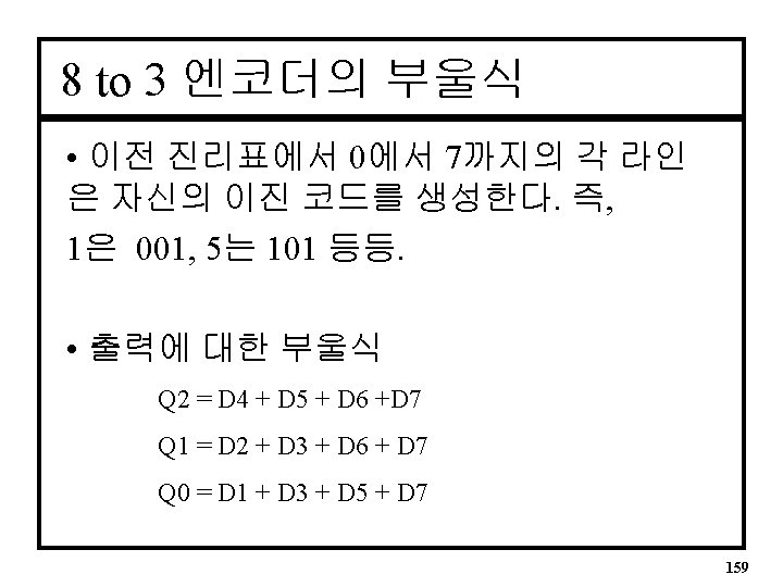
8 to 3 엔코더 진리표 • 입력은 Active High D 7 D 6 D 5 D 4 D 3 D 2 D 1 D 0 Q 2 Q 1 Q 0 0 0 0 1 0 0 0 0 0 1 0 0 0 0 1 0 0 1 1 | 0 0 | 0 1 158
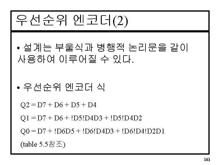
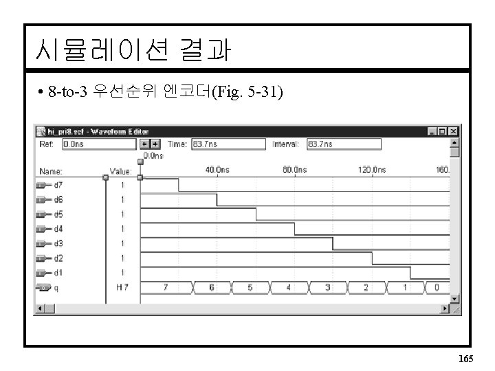
우선순위 엔코더의 VHDL Architecture • 8 to 3 우선순위 엔코더의 간략한 예 ENTITY hi_pri 8 a IS PORT( d : IN BIT_VECTOR(7 downto 0); q : OUT BIT_VECTOR(2 downto 0)); END hi_pri 8 a ; ARCHITECTURE priorenc OF enc 8 to 3 IS BEGIN -- concurrent signal assignments Q(2) <= D(7) OR D(6) OR D(5) OR D(4); Q(1) <= D(7) OR D(6) OR ((not D(5)) and (not D(4)) and D(3)) OR ((not D(5)) and (not D(4)) and D(2)) ; Q(0) <= -- In a similar fashion END priorenc; 162
다른 VHDL Encoder(1) • A WHEN ELSE is similar to If-Then-Else. ENTITY hi_pri 8 a IS PORT( d : IN BIT_VECTOR(7 downto 0); q : OUT INTEGER RANGE 0 to 7); END hi_pri 8 a ; ARCHITECTURE a OF hi_pri 8 b IS BEGIN -- conditional signal assignments Q <= 7 WHEN D(7) = ‘ 1’ ELSE -- The highest-priority condition is examined first 6 WHEN D(6) = ‘ 1’ ELSE 5 WHEN D(5) = ‘ 1’ ELSE 4 WHEN D(4) = ‘ 1’ ELSE 3 WHEN D(3) = ‘ 1’ ELSE 2 WHEN D(2) = ‘ 1’ ELSE 1 WHEN D(1) = ‘ 1’ ELSE 0; END a; 163
다른 VHDL Encoder(2) • If-Then-Else문은 반드시 PROCESS문 내에만 사용된다. ENTITY hi_pri 8 a IS PORT( d : IN BIT_VECTOR(7 downto 0); q : OUT INTEGER RANGE 0 to 7); END hi_pri 8 a ; ARCHITECTURE a OF hi_pri 8 b IS BEGIN PROCESS (d) BEGIN IF (d(7) = ‘ 1’) THEN q <= 7; ELSIF (d(6) = ‘ 1’) THEN q <= 6; --ELSIF (d(1) = ‘ 1’) THEN q <= 1; ELSE q <= 0; ENDIF; END PROCESS; END a; 164
4: 1 Multiplexers (Fig 5. 34 & 5. 37) Y = D 0!S 1!S 0 + D 1!S 1 S 0 + D 2 S 1!S 0 + D 3 S 1 S 0 167
4: 1 MUX(프로세스내의 case문) ARCHITECTURE mux 4 to 1 OF mux 4 case IS BEGIN PROCESS(S) -- Process is sensitive to S (S 1, S 0) Selects BEGIN CASE S IS WHEN “ 00” => Y <= D 0; WHEN “ 01” => Y <= D 1; WHEN “ 10” => Y <= D 2; WHEN “ 11” => Y <= D 3; WHEN OTHERS => Y <= ‘ 0’; END CASE; END PROCESS; END mux 4 to 1; 169
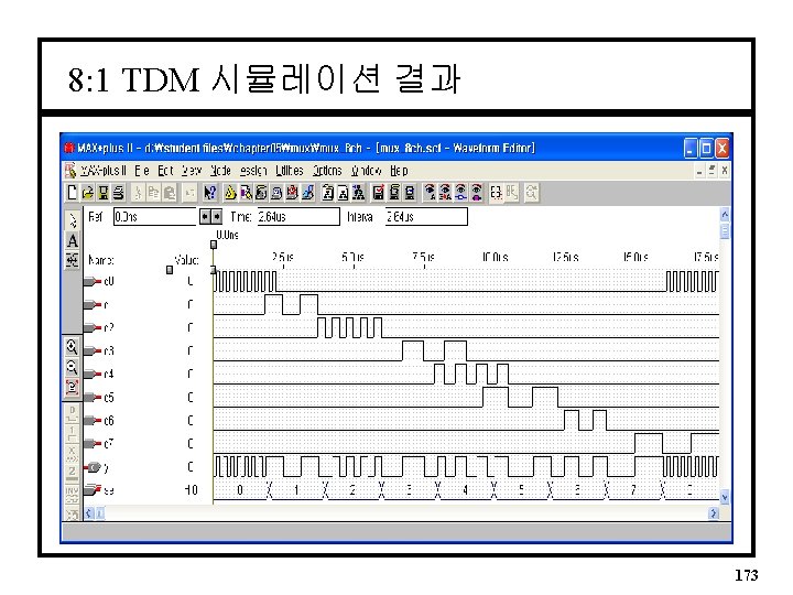
8: 1 TDM ENTITY mux_8 ch IS PORT( sel : IN BIT_VECTOR(2 downto 0); d : IN BIT_VECTOR(7 downto 0); y : OUT BIT); END mux_8 ch; ARCHITECTURE a OF mux_8 ch IS BEGIN -- Selected Signal Assignment MUX 8: WITH sel SELECT y <= d(0) WHEN "000", d(1) WHEN "001", d(2) WHEN "010", d(3) WHEN "011", d(4) WHEN "100", d(5) WHEN "101", d(6) WHEN "110", d(7) WHEN "111"; END a; 172
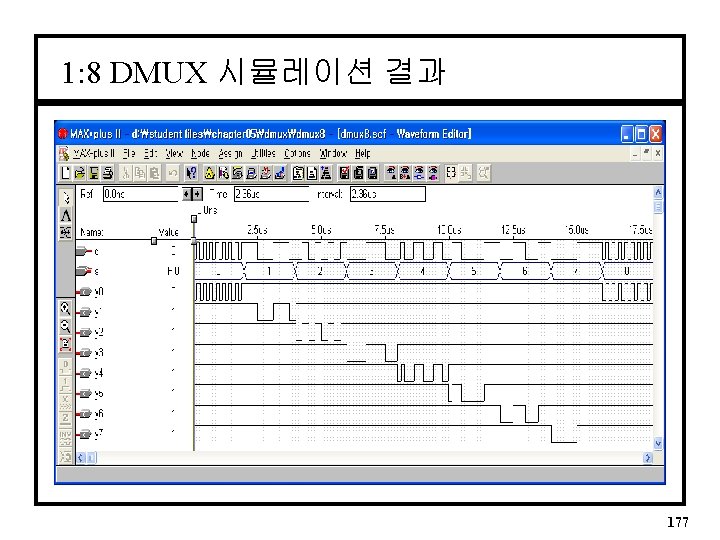
1: 8 DMUX ENTITY dmux 8 IS PORT( s : IN d : IN y : OUT INTEGER Range 0 to 7; BIT_VECTOR (0 to 7)); END dmux 8; ARCHITECTURE a OF dmux 8 IS SIGNAL output : BIT_VECTOR(0 to 7); BEGIN PROCESS (d, s) BEGIN IF (d = '1') THEN output <= "1111"; ELSE CASE s IS WHEN 0 => output <= "01111111"; WHEN 1 => output <= "10111111"; WHEN 2 => output <= "11011111"; WHEN 3 => output <= "11101111"; WHEN 4 => output <= "11110111"; WHEN 5 => output <= "11111011"; WHEN 6 => output <= "11111101"; WHEN 7 => output <= "11111110"; WHEN OTHERS => output <= "1111"; END CASE; END IF; y <= output; END PROCESS; END a; 176
2 -Bit 크기 비교기 VHDL(concurrent) -- compare 2. vhd (It is difficult to type because of too many parenthesis) ENTITY compare 2 IS PORT( a, b : IN agtb, aeqb, altb BIT_VECTOR(1 downto 0); : OUT BIT); END compare 2; ARCHITECTURE a OF compare 2 IS BEGIN altb <= (not (a(1)) and b(1)) or ((not (a(1) xor b(1))) and (not (a(0)) and b(0))); aeqb<= (not (a(1) xor b(1))) and (not (a(0) xor b(0))); agtb<= (a(1) and not (b(1))) or ((not (a(1) xor b(1))) and (a(0) and not (b(0)))); END a; 181
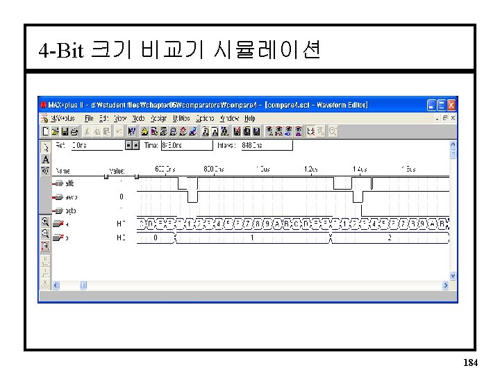
4 -Bit 크기 비교기 VHDL(behavioral) LIBRARY ieee; USE ieee. std_logic_1164. ALL; ENTITY compare 4 IS PORT( a, b : IN INTEGER RANGE 0 TO 15; -- for 8 -bit 0 TO 255 agtb, aeqb, altb : OUT STD_LOGIC); END compare 4; ARCHITECTURE a OF compare 4 IS SIGNAL compare : STD_LOGIC_VECTOR(2 downto 0); BEGIN 182
4 -Bit 크기 비교기 VHDL(계속) PROCESS (a, b) -- Sensitive to A and B Integer Arrays BEGIN IF a < b THEN compare <= “ 110”; q Relational operators ELSIF a = b THEN = = compare <= “ 101”; ¹ /= ELSIF a > b THEN ³ >= compare <= “ 011”; <= ELSE compare <= “ 111”; END IF; agtb <= compare(2); aeqb <= compare(1); altb <= compare(0); END PROCESS; END a; in VHDL 183
패리티VHDL Architecture • Six Bit Parity Generator ARCHITECTURE par OF pargen IS BEGIN parev <= A 0 XOR A 1 XOR A 2 XOR A 3 XOR A 4 XOR A 5; END par; 191
SUMMARY • A selected signal assignment statement __label: WITH __expression SELECT __signal <= __expression WHEN __constant_value, __expression WHEN __constant_value; • A conditional signal assignment statement __label: __signal <= __expression WHEN __boolean_expression ELSE __expression; • SIGNAL act as internal connections in a VHDL design entity. They can be single lines or vectors and are declared before the BEGIN clause of an ARCHITECTURE body. 192