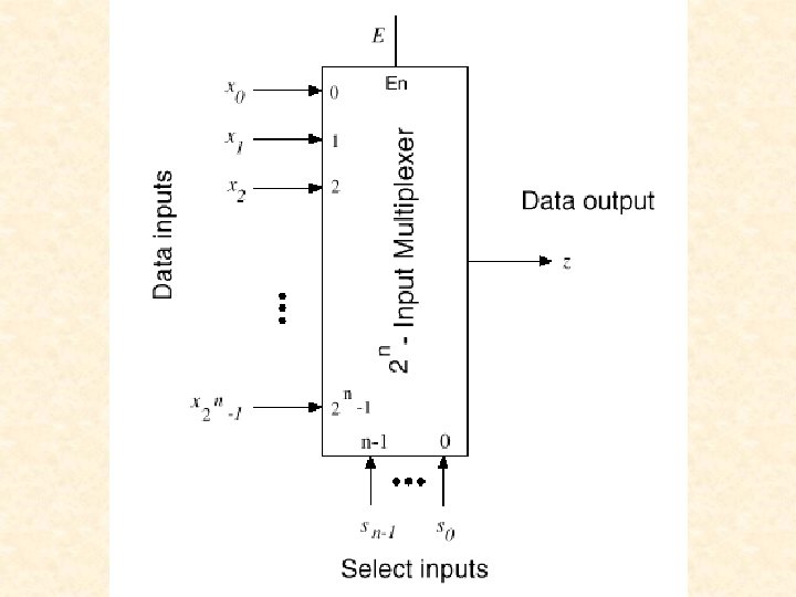
Multiplexers Section 3 7 Mano Kime Multiplexers Demultiplexers

 • Lab 1 – Behavioral VHDL -- Multiplexers")


 • Lab 1 – Behavioral VHDL -- Multiplexers • MUX")
 b(n-1: 0) n-line 2 x")
 n-line 2 x 1 MUX y(n-1:")


; port")
 b(n-1 : 0) c(n-1 : 0)")


 <variable declarations> begin <sequential statements> end process")
 • Lab 1 – Behavioral VHDL -- Multiplexers • MUX")


")
 Start with any variable")
 Then x! for example")
 Then x 2 for")
 Inputs x 0 =")
 MUX Select Lines x")


 • Starting with x")
 • Starting with x")

- Slides: 48
Multiplexers Section 3 -7 Mano & Kime
Multiplexers & Demultiplexers • Multiplexers (Selectors) • Lab 1 – Behavioral VHDL -- Multiplexers • MUX as a Universal Element
4– to– 1 - Line Multiplexer
4–to– 1 -Line Multiplexer with Transmission Gates
Quadruple 2–to– 1 -Line Multiplexer
Typical uses
Multiplexers • Multiplexers (Selectors) • Lab 1 – Behavioral VHDL -- Multiplexers • MUX as a Universal Element
Combinational Circuit Example n-line 2 -to-1 Multiplexer a(n-1: 0) b(n-1: 0) n-line 2 x 1 MUX sel y(n-1: 0) sel 0 1 y a b
An n-line 2 x 1 MUX a(n-1: 0) n-line 2 x 1 MUX y(n-1: 0) library IEEE; use IEEE. std_logic_1164. all; b(n-1: 0) entity mux 2 g is sel generic (width: positive); port ( a: in STD_LOGIC_VECTOR(width-1 downto 0); b: in STD_LOGIC_VECTOR(width-1 downto 0); sel: in STD_LOGIC; y: out STD_LOGIC_VECTOR(width-1 downto 0) ); end mux 2 g;
Entity Each entity must begin with these library and use statements library IEEE; use IEEE. std_logic_1164. all; generic statement defines width of bus entity mux 2 g is generic (width: positive); port ( a: in STD_LOGIC_VECTOR(width-1 downto 0); b: in STD_LOGIC_VECTOR(width-1 downto 0); sel: in STD_LOGIC; y: out STD_LOGIC_VECTOR(width-1 downto 0) ); end mux 2 g; port statement defines inputs and outputs
Entity Mode: in or out library IEEE; use IEEE. std_logic_1164. all; entity mux 2 g is generic (width: positive); port ( a: in STD_LOGIC_VECTOR(width-1 downto 0); b: in STD_LOGIC_VECTOR(width-1 downto 0); sel: in STD_LOGIC; y: out STD_LOGIC_VECTOR(width-1 downto 0) ); end mux 2 g; Data type: STD_LOGIC, STD_LOGIC_VECTOR(width-1 downto 0);
Standard Logic library IEEE; use IEEE. std_logic_1164. all; type std_ulogic is ( ‘U’, ‘X’ ‘ 0’ ‘ 1’ ‘Z’ ‘W’ ‘L’ ‘H’ ‘-’); -- Uninitialized -- Forcing unknown -- Forcing zero -- Forcing one -- High impedance -- Weak unknown -- Weak zero -- Weak one -- Don’t care
Standard Logic Type std_ulogic is unresolved. Resolved signals provide a mechanism for handling the problem of multiple output signals connected to one signal. subtype std_logic is resolved std_ulogic;
Architecture architecture mux 2 g_arch of mux 2 g is begin mux 2_1: process(a, b, sel) begin a(n-1: 0) if sel = '0' then y <= a; b(n-1: 0) else y <= b; end if; end process mux 2_1; end mux 2 g_arch; n-line 2 x 1 MUX y(n-1: 0) sel Note: <= is signal assignment
Architecture entity name process sensitivity architecture mux 2 g_arch of mux 2 g is list begin mux 2_1: process(a, b, sel) begin Sequential statements if sel = '0' then (if…then…else) must y <= a; be in a process else y <= b; end if; end process mux 2_1; end mux 2 g_arch; Note begin…end in architecture Note begin…end in process
Digilab 2 – DIO 1 Boards Pushbutton bn Four 7 -segment displays 4 Pushbuttons BTN Spartan II FPGA 8 LEDs LD 8 Switches SW 74 HC 373 latch ldg <= ‘ 1’
Top-level Design – Lab 1
library IEEE; use IEEE. std_logic_1164. all; entity lab 1 is port ( SW: in STD_LOGIC_VECTOR (1 to 8); BTN 4: in STD_LOGIC; ldg: out STD_LOGIC; LD: out STD_LOGIC_VECTOR (1 to 4) ); end lab 1;
architecture lab 1_arch of lab 1 is component mux 2 g generic(width: positive); port ( a: in STD_LOGIC_VECTOR (width-1 downto 0); b: in STD_LOGIC_VECTOR (width-1 downto 0); sel: in STD_LOGIC; y: out STD_LOGIC_VECTOR (width-1 downto 0) ); end component; constant bus_width: positive : = 4; begin ldg <= '1'; -- enable 74 HC 373 latch SWmux: mux 2 g generic map(width => bus_width) port map (a => SW(1 to 4), b => SW(5 to 8), sel => BTN 4, y => LD); end lab 1_arch;
An n-line 4 x 1 multiplexer a(n-1: 0) b(n-1 : 0) c(n-1 : 0) d(n-1 : 0) 8 -line 4 x 1 MUX sel(1: 0) y(n-1 : 0) Sel “ 00” “ 01” “ 10” “ 11” y a b c d
An 8 -line 4 x 1 multiplexer library IEEE; use IEEE. std_logic_1164. all; entity mux 4 g is generic(width: positive); port ( a: in STD_LOGIC_VECTOR (width-1 downto 0); b: in STD_LOGIC_VECTOR (width-1 downto 0); c: in STD_LOGIC_VECTOR (width-1 downto 0); d: in STD_LOGIC_VECTOR (width-1 downto 0); sel: in STD_LOGIC_VECTOR (1 downto 0); y: out STD_LOGIC_VECTOR (width-1 downto 0) ); end mux 4 g;
Example of case statement architecture mux 4 g_arch of mux 4 g is begin Note implies operator => process (sel, a, b, c, d) begin case sel is Sel y when "00" => y <= a; “ 00” a when "01" => y <= b; “ 01” b when "10" => y <= c; when others => y <= d; “ 10” c end case; “ 11” d end process; end mux 4 g_arch; Must include ALL posibilities in case statement
VHDL Architecture Structure architecture name_arch of name is Signal assignments begin Processes contain sequential Concurrent statements, but execute concurrently within the Process 1 architecture body Concurrent statements Process 2 Concurrent statements end name_arch;
VHDL Process P 1: process (<sensitivity list) <variable declarations> begin <sequential statements> end process P 1; Within a process: Variables are assigned using : = Optional process label and are updated immediately. Signals are assigned using <= and are updated at the end of the process.
Multiplexers • Multiplexers (Selectors) • Lab 1 – Behavioral VHDL -- Multiplexers • MUX as a Universal Element
Multiplexer as universal combinational module • connect input variables x to select inputs of multiplexer s • set data inputs to multiplexer equal to values of function for corresponding assignment of select variables • using a variable at data inputs reduces size of the multiplexer
Implementing a Boolean Function with a Multiplexer
Implementing a Four- Input Function with a Multiplexer
Networks with 2 -input multiplexers
Implementation of SFs with network of MUXes
Design of networks with MUXes
Example
Ordering of variables in subtrees affects the number of MUXes
Example of Shannon’s Decomposition F = x 3(x 1 + x 2 x 0) Implemented using a multiplexer network
F = x 3(x 1 + x 2 x 0) Start with any variable - x 0 for example x 0 = 0 F = x 3 x 1 x 0 = 1 F = x 3(x 1 + x 2)
F = x 3(x 1 + x 2 x 0) Then x! for example x 0 = 0 F = x 3 x 1 x 0 = 1 F = x 3(x 1 + x 2) x 1 = 0 F=0 x 1 = 1 F = x 3 x 1 = 0 F = x 3 x 2 x 1 = 1 F = x 3
F = x 3(x 1 + x 2 x 0) Then x 2 for example x 0 = 0 F = x 3 x 1 x 0 = 1 F = x 3(x 1 + x 2) x 1 = 0 F=0 x 1 = 1 F = x 3 x 1 = 0 F = x 3 x 2 x 1 = 1 F = x 3 x 2 = 0 F=0 x 2 = 1 F = x 3
F = x 3(x 1 + x 2 x 0) Inputs x 0 = 0 F = x 3 x 1 x 0 = 1 F = x 3(x 1 + x 2) x 1 = 0 F=0 x 1 = 1 F = x 3 x 1 = 0 F = x 3 x 2 x 1 = 1 F = x 3 x 2 = 0 F=0 x 2 = 1 F = x 3
F = x 3(x 1 + x 2 x 0) MUX Select Lines x 0 = 0 F = x 3 x 1 x 0 = 1 F = x 3(x 1 + x 2) x 1 = 0 F=0 x 1 = 1 F = x 3 x 1 = 0 F = x 3 x 2 x 1 = 1 F = x 3 x 2 = 0 F=0 x 2 = 1 F = x 3
x 0 = 0 F = x 3 x 1 x 0 = 1 F = x 3(x 1 + x 2) x 1 = 0 F=0 x 1 = 1 F = x 3 x 1 = 0 F = x 3 x 2 x 1 = 1 F = x 3 x 2 = 0 F=0 x 2 = 1 F = x 3 x 1 0 F 1 x 3(x 1 + x 2) sel x 0
x 0 = 0 F = x 3 x 1 x 0 = 1 F = x 3(x 1 + x 2) x 1 = 0 F=0 x 1 = 1 F = x 3 x 1 = 0 F = x 3 x 2 x 1 = 1 F = x 3 x 2 = 0 F=0 x 2 = 1 F = x 3 x 1 0 0 x 3 1 sel x 1 The branch for x 0 = 0 0 F 1 x 3(x 1 + x 2) sel x 0
x 0 = 0 F = x 3 x 1 x 0 = 1 F = x 3(x 1 + x 2) x 1 = 0 F=0 x 1 = 1 F = x 3 x 1 = 0 F = x 3 x 2 x 1 = 1 F = x 3 The branch for x 0 = 1 x 2 = 0 F=0 x 2 = 1 F = x 3 x 1 0 0 x 3 1 sel x 1 0 F 1 x 3 x 2 0 x 3 1 sel x 0 x 3(x 1 + x 2)
x 0 = 0 F = x 3 x 1 x 0 = 1 F = x 3(x 1 + x 2) x 1 = 0 F=0 x 1 = 1 F = x 3 x 2 = 0 F=0 x 1 = 0 F = x 3 x 2 = 1 F = x 3 x 1 = 1 F = x 3 The branch for x 1 = 0 x 3 x 1 0 0 x 3 1 sel x 1 0 0 0 F 1 sel 0 x 3 1 sel x 2 x 3 1 sel x 1 x 0 x 3(x 1 + x 2)
F = x 3(x 1 + x 2 x 0) • Starting with x 0 • Shannon’s Decomposition 0 0 • 4 x 3 1 Multiplexers sel x 1 0 0 0 F 1 sel 0 x 3 1 sel x 2 x 3 1 sel x 1 x 0
F = x 3(x 1 + x 2 x 0) • Starting with x 1 • Shannon’s Decomposition • 3 Multiplexers 0 0 0 x 3 1 0 1 sel 0 x 0 F sel x 2 x 3 1 sel x 1
16 -input tree multiplexer