Unit D Topic 2 INSULATORS AND CONDUCTORS Insulators


")


 An electric stove is connected to a 240 V outlet. If the")
 A 30 V battery creates a current through a 15 Ω resistor.")


- Slides: 31
Unit D Topic 2
INSULATORS AND CONDUCTORS • Insulators: made when the electrons are tightly bound to the nucleus of the atom. They resist movement from the nucleus • Conductors: made when the electrons are freer to move they will only flow if the materials is hooked to an electrical source • The electrons will flow when voltage is applied
SUPERCONDUCTORS • Elements like gold, silver and copper are all excellent conductors, but they are not perfect. Electrons still meet some resistance as they travel through them. • Superconductors are perfect conductors, they have no resistance to electron flow. • Example) Mercury at absolute zero (-273°C)
SEMI-CONDUCTORS • It is not always easy to label a substance as a conductor or insulator • Semiconductors are somewhere in between • • Act as conductors at high temperature • Act as insulators at low temperature Germanium and silicon are examples of semiconductors
RESISTANCE • • Resistance is the measure of how difficult it is for electrons to flow through a substance • Measured in Ohms (Ω) Resistance is achieved through resistors – devices having resistance to the passage of electrical current, often used to control current in a circuit
• Insulators have a high resistance to current. • Conductors have a low resistance to current. • Superconductors have no resistance to current. • Why do we use them? • • The more resistance a substance has, the more the substance gains energy from each electron that passes through it The energy gained by the substance is radiated to the surroundings as either heat or light (i. e. light bulb or space heater radiate heat and light because they have high resistance)
TYPES OF RESISTORS • A wide variety of resistors are made for different applications, especially in electronics. • Resistors can be made with a number or techniques and materials, but there are two common types • • Wire-wound – wire made of heat-resistant alloy wrapped around an insulating core Carbon-composition – made of carbon mixed with other materials and is moulded into a cylinder with a wire at each end
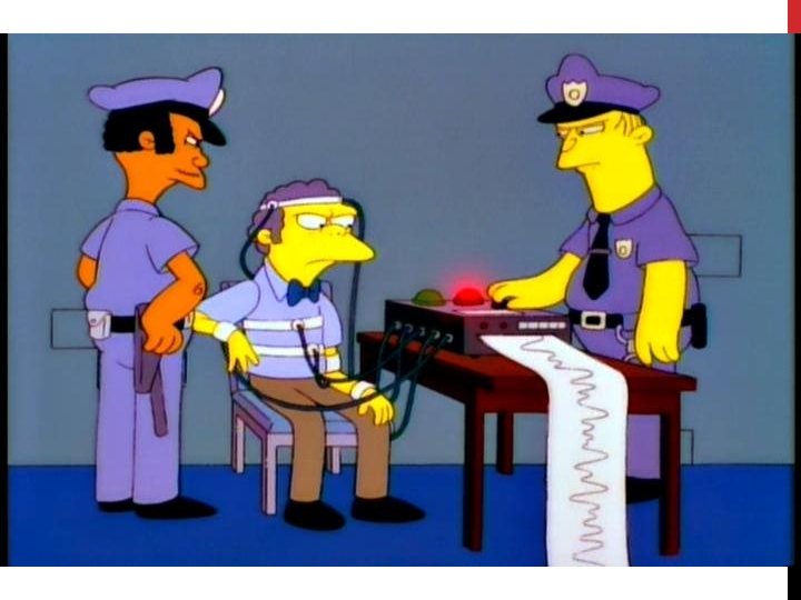
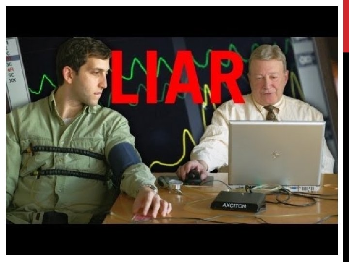
CAN RESISTORS BE IN A SOLUTION? • Yes, but the more charged particles in a solution, the better it conducts. • Does water conduct? • Distilled water (only water molecules) will not! Tap/Environmental water (water molecules and dissolved minerals) will! Sweat will – that’s how a lie detector works! • • • It measures your skins resistance which will decrease if you sweat. If you lie theory is you will be under stress and sweat which will cause an increase in conduction between the electrodes on your skin – this would show up as a peak on the graph.
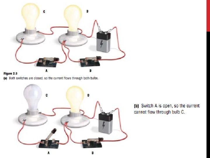
SWITCHES AND VARIABLE RESISTORS • A switch is usually the best method for turning electricity on and off in a circuit when a switch is on, two conductors are pressed together. The current can flow from one to the other. • When the switch is off, the conductors are separated and no current flows. • A variable resistor or rheostat changes the current flow gradually (eg. Dimmer switch) •
LET’S REVIEW • Current – is the movement of electrons • Voltage – is what makes the electrons move • Resistance – is what opposes the motion of electrons
FLOW OF ELECTRICITY • At this point we have learned different terms to describe electrical current. Voltage, current, resistance, conductors, and cells all describe different aspects of electron flow. Since electrons “flow” we will use a metaphor of moving water. • • • Like flowing water, electricity must come from a source. Like water smashing into rocks in rapids, electricity encounters resistance. The more water, the more powerful the current in a river – the more electrons, the more powerful the current is in a conductors For both water and electricity, the source must be constantly replenished.
• The voltage is analogous the height of the waterfall (potential energy)
OHM’S LAW • German scientist Georg Simon Ohm made exciting electrical discoveries in the early 1800 s. In 1826 he was able to link voltage (V), current (I) and resistance (R) • Ohm’s Law states that – as long as temperature stays the same, • • the resistance of conductor stays constant the current is directly proportional to the voltage applied
APPLYING OHM’S LAW • As long as two of the values are known, the third one can be calculated.
Example 1) An electric stove is connected to a 240 V outlet. If the current flowing through the stove is 20 A, what is the resistance of the heating element?
Example 2) A 30 V battery creates a current through a 15 Ω resistor. How much current is created? Example 3) A motor has an internal resistance of 40 Ω. The motor is in a circuit with a current of 4. 0 A. What is the voltage? Example 4) A current of 625 m. A runs through a bulb that is connected to 120 V. What is the resistance of the bulb?
USING TEST METERS 1. Voltmeters • • Recall that voltage is the potential difference between two points Many electricians refer to the potential difference across a resistor or device as a voltage drop
2. Ammeters • • • Are used to measure electric current in amperes Measures how many electrons move past a point in a circuit each second so it must be placed into the current Meters used to measure small currents are sometimes called galvanometers
3. Multimeters • Are used to measure voltage, current or resistance in a circuit by turning a selector switch
ANALYZING AND BUILDING ELECTRICAL CIRCUITS • A Circuit is a path for electrons to flow through. • • The path is from a power sources negative terminal, through the various components and on to the positive terminal. The paths may vary off here and there but they always form a path from the negative to positive
COMPONENTS OF A CIRCUIT 1. Electrical Source – provides energy and a supply of electrons for the circuit 2. Conductor – provides a path for current 3. Switching Mechanism – controls current flow, turning it on and off, or directing it into different parts of the circuit 4. Load – converts electrical energy into some other form of energy
In your textbook go to page 312 and fill in the chart in your notes. Symbol Represents Description
2 TYPES OF CIRCUITS – SERIES • A series circuit is one with all the loads in a row, like links in a chain. • • There is only one path for the electricity to flow. If one part of the circuit malfunctions – like a bulb burns out – the whole circuit shuts down. Adding components increases the total resistance of the circuit, this decreases the current. Adding an extra light bulb makes all the light bulbs in the circuit get dimmer.
2 TYPES OF CIRCUITS – PARALLEL • A parallel circuits is one that has two or more paths for the electricity to flow • • • The loads are parallel to each other. If a load in this circuit malfunctions, the other loads continue to work as there is still a path from the negative to positive terminals of the battery. If you add a new pathway with more resistance it does not affect the resistance in any of the other paths.
SOME EXAMPLES A handheld mixer with variable speeds. • Is this a series or a parallel circuit? • What path(s) can electricity travel and in which direction? • What are the components of the circuit? • Do all the loads have to be “on” at the same time?
An ATV circuit with a motor and headlights. • Is this a series or a parallel circuit? • What path(s) can electricity travel and in which direction? • What are the components of the circuit? • Do all the loads have to be “on” at the same time?
CIRCUITS IN OUR HOMES • House Wiring • • Homes are wired in parallel Each load (appliance, light, etc. ) can be turned on or off independently Each load is controlled with its own switch All the switches in a circuit are in series and are controlled by one breaker
MICROCIRCUITS • Conventional switches are practical and convenient for a home but for the tiny circuits in advanced electronics applications, transistors must be used instead Device usually with three layers arranged such that a small voltage through the middle layer controls the current between the outer layers, allowing the device to act as a switch or amplifier Microcircuits (also called integrated circuits) are made up of microscopic transistors and resistors. • • • Is a circuit on an extremely small scale