Underwater Tracking System Francesco Simeone francesco simeoneroma 1


- Slides: 30
Underwater Tracking System Francesco Simeone (francesco. simeone@roma 1. infn. it) 9 Marzo 2015
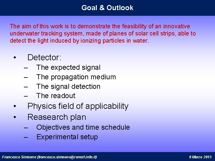
Goal & Outlook The aim of this work is to demonstrate the feasibility of an innovative underwater tracking system, made of planes of solar cell strips, able to detect the light induced by ionizing particles in water. • Detector: – – • • The expected signal The propagation medium The signal detection The readout Physics field of applicability Reasearch plan – – Objectives and time schedule Experimental setup Francesco Simeone (francesco. simeone@roma 1. infn. it) 9 Marzo 2015
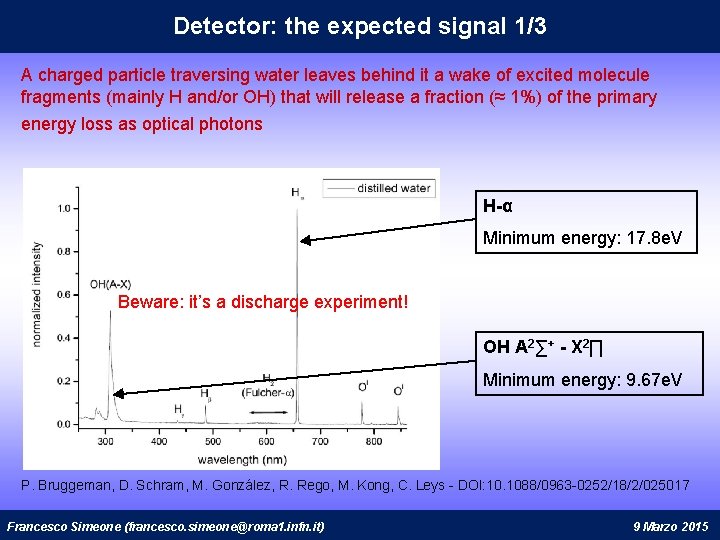
Detector: the expected signal 1/3 A charged particle traversing water leaves behind it a wake of excited molecule fragments (mainly H and/or OH) that will release a fraction (≈ 1%) of the primary energy loss as optical photons H-α Minimum energy: 17. 8 e. V Beware: it’s a discharge experiment! OH A 2∑+ - X 2∏ Minimum energy: 9. 67 e. V P. Bruggeman, D. Schram, M. González, R. Rego, M. Kong, C. Leys - DOI: 10. 1088/0963 -0252/18/2/025017 Francesco Simeone (francesco. simeone@roma 1. infn. it) 9 Marzo 2015
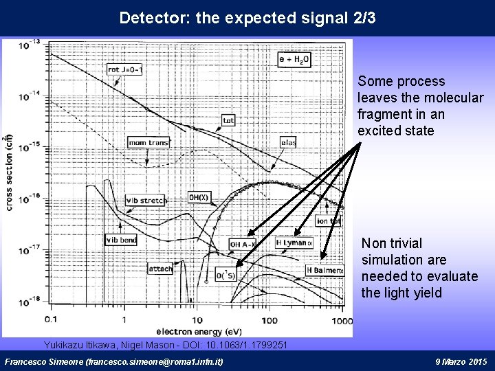
Detector: the expected signal 2/3 Some process leaves the molecular fragment in an excited state Non trivial simulation are needed to evaluate the light yield Yukikazu Itikawa, Nigel Mason - DOI: 10. 1063/1. 1799251 Francesco Simeone (francesco. simeone@roma 1. infn. it) 9 Marzo 2015
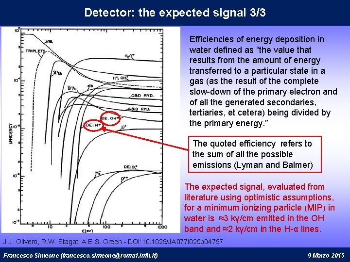
Detector: the expected signal 3/3 Efficiencies of energy deposition in water defined as “the value that results from the amount of energy transferred to a particular state in a gas (as the result of the complete slow-down of the primary electron and of all the generated secondaries, tertiaries, et cetera) being divided by the primary energy. ” The quoted efficiency refers to the sum of all the possible emissions (Lyman and Balmer) The expected signal, evaluated from literature using optimistic assumptions, for a minimum ionizing particle (MIP) in water is ≈3 kγ/cm emitted in the OH band ≈2 kγ/cm in the H-α lines. J. J. Olivero, R. W. Stagat, A. E. S. Green - DOI: 10. 1029/JA 077 i 025 p 04797 Francesco Simeone (francesco. simeone@roma 1. infn. it) 9 Marzo 2015
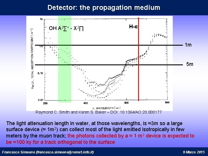
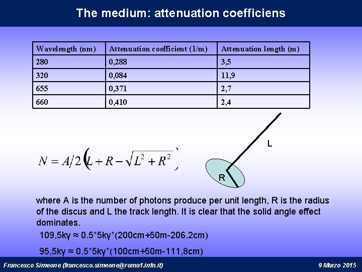
Detector: the propagation medium OH A 2∑+ - X 2∏ H-α 1 m 5 m Raymond C. Smith and Karen S. Baker – DOI: 10. 1364/AO. 20. 000177 The light attenuation length in water, at those wavelengths, is ≈3 m so a large surface device (≈ 1 m 2) can collect most of the light emitted isotropically in few meters by the muon track; the photons collected by a ≈ 1 m 2 device is expected to be ≈100 kγ for a track orthogonal to the surface Francesco Simeone (francesco. simeone@roma 1. infn. it) 9 Marzo 2015
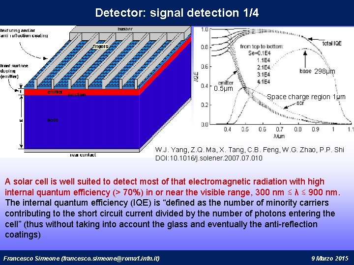
Detector: signal detection 1/4 298µm 0. 5µm Space charge region 1µm W. J. Yang, Z. Q. Ma, X. Tang, C. B. Feng, W. G. Zhao, P. P. Shi DOI: 10. 1016/j. solener. 2007. 010 A solar cell is well suited to detect most of that electromagnetic radiation with high internal quantum efficiency (> 70%) in or near the visible range, 300 nm ≲ λ ≲ 900 nm. The internal quantum efficiency (IQE) is “defined as the number of minority carriers contributing to the short circuit current divided by the number of photons entering the cell” (thus without taking into account the glass and eventually the anti-reflection coatings) Francesco Simeone (francesco. simeone@roma 1. infn. it) 9 Marzo 2015
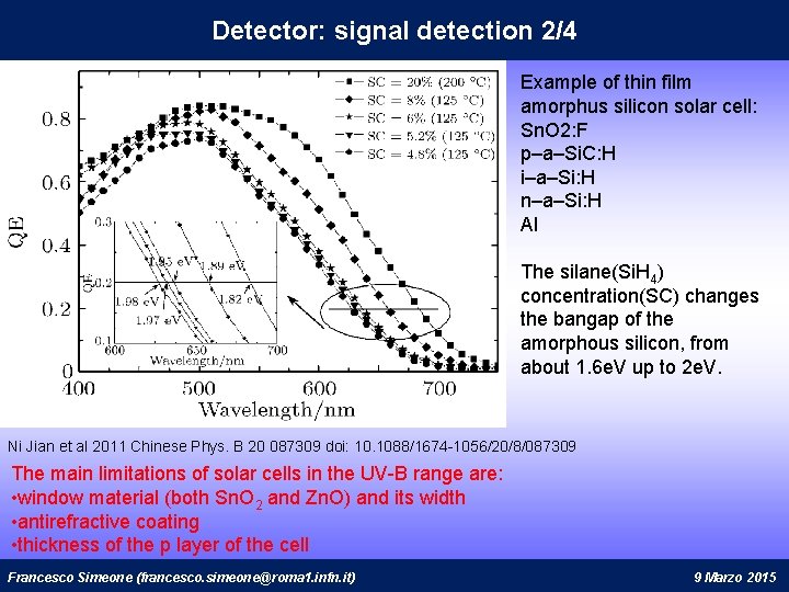
Detector: signal detection 2/4 Example of thin film amorphus silicon solar cell: Sn. O 2: F p–a–Si. C: H i–a–Si: H n–a–Si: H Al The silane(Si. H 4) concentration(SC) changes the bangap of the amorphous silicon, from about 1. 6 e. V up to 2 e. V. Ni Jian et al 2011 Chinese Phys. B 20 087309 doi: 10. 1088/1674 -1056/20/8/087309 The main limitations of solar cells in the UV-B range are: • window material (both Sn. O 2 and Zn. O) and its width • antirefractive coating • thickness of the p layer of the cell Francesco Simeone (francesco. simeone@roma 1. infn. it) 9 Marzo 2015
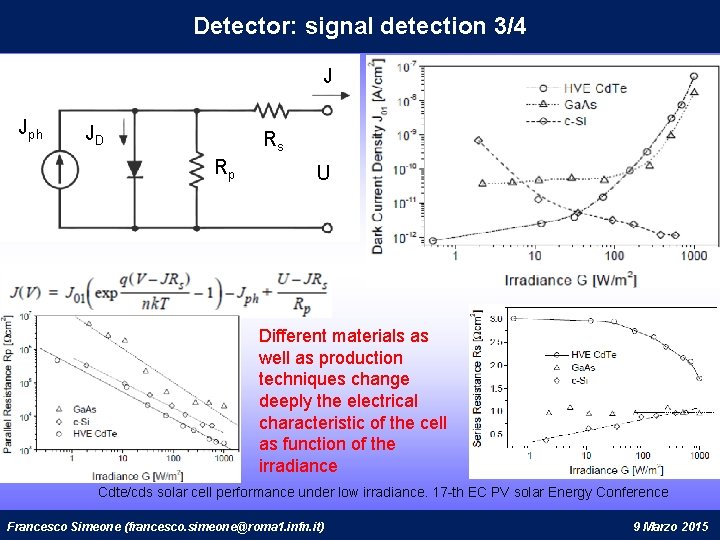
Detector: signal detection 3/4 J Jph JD Rs Rp U Different materials as well as production techniques change deeply the electrical characteristic of the cell as function of the irradiance Cdte/cds solar cell performance under low irradiance. 17 -th EC PV solar Energy Conference Francesco Simeone (francesco. simeone@roma 1. infn. it) 9 Marzo 2015
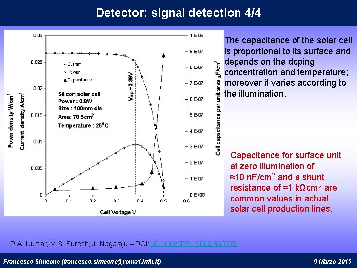
Detector: signal detection 4/4 The capacitance of the solar cell is proportional to its surface and depends on the doping concentration and temperature; moreover it varies according to the illumination. Capacitance for surface unit at zero illumination of ≈10 n. F/cm 2 and a shunt resistance of ≈1 kΩcm 2 are common values in actual solar cell production lines. R. A. Kumar, M. S. Suresh, J. Nagaraju – DOI: 10. 1109/TPEL. 2005. 869779 Francesco Simeone (francesco. simeone@roma 1. infn. it) 9 Marzo 2015
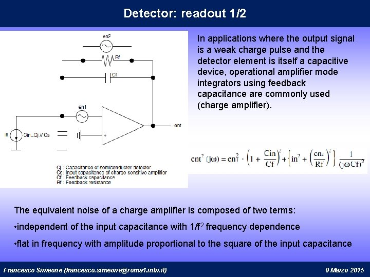
Detector: readout 1/2 In applications where the output signal is a weak charge pulse and the detector element is itself a capacitive device, operational amplifier mode integrators using feedback capacitance are commonly used (charge amplifier). The equivalent noise of a charge amplifier is composed of two terms: • independent of the input capacitance with 1/f 2 frequency dependence • flat in frequency with amplitude proportional to the square of the input capacitance Francesco Simeone (francesco. simeone@roma 1. infn. it) 9 Marzo 2015
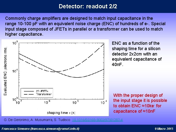
Detector: readout 2/2 Commonly charge amplifiers are designed to match input capacitance in the range 10 -100 p. F with an equivalent noise charge (ENC) of hundreds of e-. Special input stage composed of JFETs in parallel or a transformer can be used to match higher capacitance. ENC as a function of the shaping time for a silicon detector 2 x 2 cm with an equivalent capacitance of 40 n. F. With the proper design of the input stage it is possible to obtain ENC ≈10 ke- for capacitance of ≈10 n. F G. De Geronimo, A. Musumarra, S. Tudisco 10. 1016/S 0168 -9002(97)01287 -4 Francesco Simeone (francesco. simeone@roma 1. infn. it) 9 Marzo 2015
Detector: conclusion • About ≈ 1% of the energy loss by particle in water goes into light (≈5 kγ/cm for a MIP) • The light produced in few meters of track could be efficiently detected (≈100 kγ for a MIP using ≈1 m 2 detector) • A solar cell, without polarization, could be used as light detector with high IQE (≈70%, about 10 f. C, over the useful wavelengths) • A specifically designed charge amplifier could be used to acquire the signal. (≈10 ke- ENC for an input capacitance ≈40 n. F) These considerations led to propose a detection device composed by a series of many small solar cells (≈1 cm 2) so that the input capacitance seen by the amplifier will be the single cell capacitance, i. e. few tens of n. F. In case of MIPs in water S/N greater than 4 seems feasible. Francesco Simeone (francesco. simeone@roma 1. infn. it) 9 Marzo 2015
Physics field of applicability As detector in water (High energy neutrinos >Ge. V) It appears possible to build a detector unit, able to measure the track of muons with energy in the range 1 -10 Ge. V, made of planes of about 10 x 10 m 2 consisting of two layers of 10 strips 10 x 1 m 2, spaced by 4 m with an active volume of about 10 kton. This detection unit will be relatively cheap since the solar cell has a low price/surface ratio and all the relevant detector components, except the electronics, could be placed directly in water, thus reducing the cables, connectors and vessel cost. Long baseline oscillation appearance experiments: Mass hierarchy and CP phase source: accelerator neutrinos baseline ~ 1000 km or longer LBNE-LAr (USA), LBNO (EU), Hyper-K (Japan) Long baseline oscillation disappearance experiments: Mass hierarchy source: atmospheric neutrinos PINGU (South-pole), ORCA (EU) Francesco Simeone (francesco. simeone@roma 1. infn. it) 9 Marzo 2015
Physics field of applicability If this feasibility study will produce positive results, other experiments, based on liquid scintillator such LENA, could take benefit from the use of solar cell as light detectors; As detector in liquid scintillator(Low energy neutrinos >Me. V) Short baseline appearance experiments: CP phase source: neutrinos from stopped pions baseline ~ 30 km low energies (E ~ 30 Me. V) LENA, Water-Cherenkov Proton decay, Geo neutrinos, Solar neutrinos CNO (LENA) As sub-detector Moreover the same effect, measured with the same device, could be used in many sub-detectors (i. e. Cherenkov tank of the Pierre Auger Observatory; LAAHSO experiment) when a cheap muon detector or a rough calorimeter of about few tons is required. Francesco Simeone (francesco. simeone@roma 1. infn. it) 9 Marzo 2015
Reasearch plan: objectives Objectives and time schedule The objectives of this proposal are twofold: Objective 1: Verify that the claimed scintillation effect in water has the potential to be used (O 1). Objective 2: Demonstrate that a device made of solar cells could efficiently measure this effect (O 2). First year: • Measure the claimed effect • Measure the electrical characteristics of different type of commercial solar cells • Measure the lowest detectable optical signal for a detector made of solar cells Second year: • Develop the proper input stage for the charge amplifier • Production of prototipal solar cell with different characteristics (ARC, window material and thickness) • Measure the claimed effect with the designed electronic Francesco Simeone (francesco. simeone@roma 1. infn. it) 9 Marzo 2015
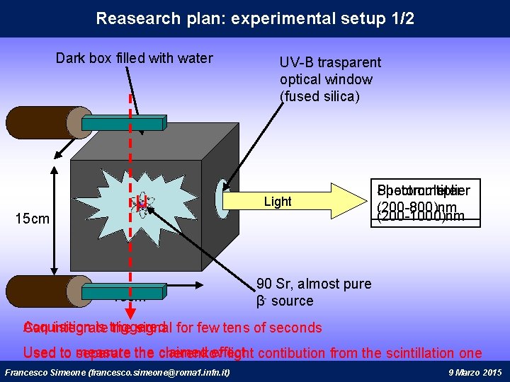
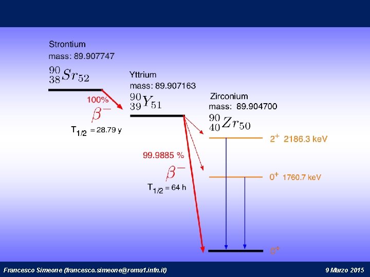
Reasearch plan: experimental setup 1/2 Dark box filled with water UV-B trasparent optical window (fused silica) 15 cm µ 15 cm Light Spectrometer Photomultiplier (200 -800)nm (200 -1000)nm 90 Sr, almost pure β- source Acquisition is triggered Can integrate the signal for few tens of seconds Used to measure the claimed effect Used to separate the cherenkov light contibution from the scintillation one Francesco Simeone (francesco. simeone@roma 1. infn. it) 9 Marzo 2015
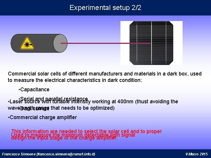
Experimental setup 2/2 Commercial solar cells of different manufacturers and materials in a dark box, used to measure the electrical characteristics in dark condition: • Capacitance • Serial and parallel resistance • Laser source with tunable intensity working at 400 nm (thust avoiding the wavelength range that needs to be optimized) • Dark current • Commercial charge amplifier This information are needed to select the solar cell and to proper Used to measure the minimum detectable ligth signal design the input stage of the charge amplifier. Francesco Simeone (francesco. simeone@roma 1. infn. it) 9 Marzo 2015
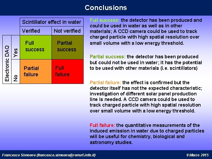
Conclusions Scintillator effect in water Yes No Electronic DAQ Verified Full success Partial failure Not verified Partial success Full failure Full success: the detector has been produced and could be used in water as well as in other materials; A CCD camera could be used to track charged particle with high spatial resolution over small volume with a low energy threshold. Partial success: the detector has been produced but could not be used in water; it has the potential to be used with other materials (i. e. scintillators) Partial failure: the effect is confirmed but the detector itself has not the expected characteristic; investigation of different solar panel production line is needed. A CCD camera could be used to track charged particle with high spatial resolution over small volume with a low energy threshold. Full failure: the quantitative measurements of the induced emission in water due to charged particles will be useful for chemistry, biological and astronomy studies. Francesco Simeone (francesco. simeone@roma 1. infn. it) 9 Marzo 2015
BACKUP Francesco Simeone (francesco. simeone@roma 1. infn. it) 9 Marzo 2015
Reasearch plan: objectives and reasearch units The objectives of this proposal are twofold: Objective 1: Verify that the claimed scintillation effect in water has the potential to be used (O 1). Objective 2: Demonstrate that a device made of solar cells could efficiently measure this effect (O 2). RU 1: This unit will coordinate the others RUs and will realize most of the experimental setups and will perform most of the data analysis. RU 1 is composed by one member, Francesco Simeone principal investigator of this proposal. RU 2: This unit will perform all the electronic development needed to fulfil this proposal. RU 2 is composed by one member, Fabrizio Ameli, INFN researcher with experience in the front-end electronic design and development as well as VHDL coding on FPGA systems. RU 3: This unit will contribute to the experimental setup needed to measure the electromagnetic radiation emitted due to dissociative excitation of the water molecules and will perform its simulation; RU 3 is composed by one member, Paolo Postorino associate professor of the physics department at “Sapienza” university, he’s an experimental physicist expert in infrared and Raman spectroscopy. Francesco Simeone (francesco. simeone@roma 1. infn. it) 9 Marzo 2015
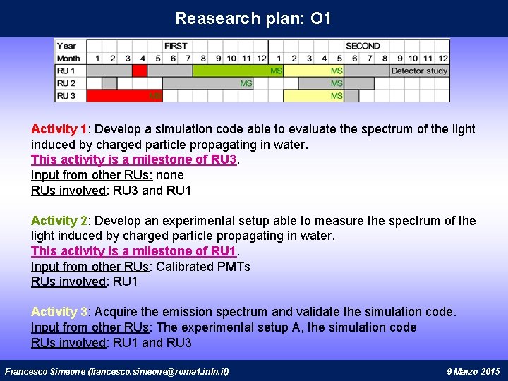
Reasearch plan: O 1 Activity 1: Develop a simulation code able to evaluate the spectrum of the light induced by charged particle propagating in water. This activity is a milestone of RU 3. Input from other RUs: none RUs involved: RU 3 and RU 1 Activity 2: Develop an experimental setup able to measure the spectrum of the light induced by charged particle propagating in water. This activity is a milestone of RU 1. Input from other RUs: Calibrated PMTs RUs involved: RU 1 Activity 3: Acquire the emission spectrum and validate the simulation code. Input from other RUs: The experimental setup A, the simulation code RUs involved: RU 1 and RU 3 Francesco Simeone (francesco. simeone@roma 1. infn. it) 9 Marzo 2015
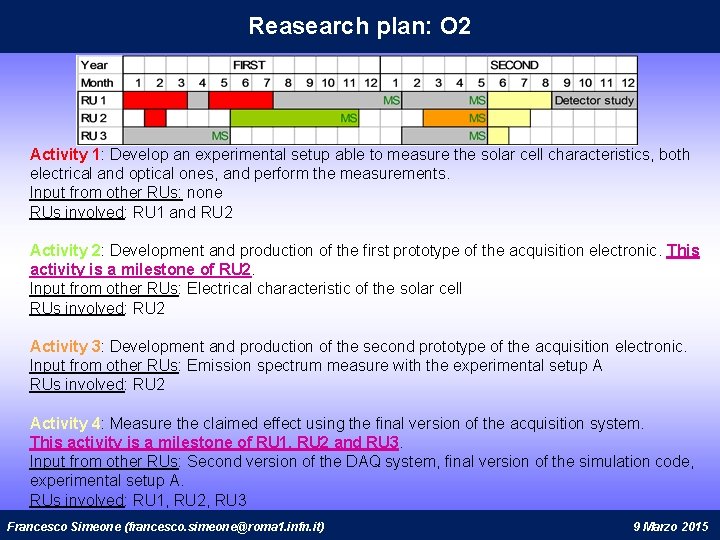
Reasearch plan: O 2 Activity 1: Develop an experimental setup able to measure the solar cell characteristics, both electrical and optical ones, and perform the measurements. Input from other RUs: none RUs involved: RU 1 and RU 2 Activity 2: Development and production of the first prototype of the acquisition electronic. This activity is a milestone of RU 2. Input from other RUs: Electrical characteristic of the solar cell RUs involved: RU 2 Activity 3: Development and production of the second prototype of the acquisition electronic. Input from other RUs: Emission spectrum measure with the experimental setup A RUs involved: RU 2 Activity 4: Measure the claimed effect using the final version of the acquisition system. This activity is a milestone of RU 1, RU 2 and RU 3. Input from other RUs: Second version of the DAQ system, final version of the simulation code, experimental setup A. RUs involved: RU 1, RU 2, RU 3 Francesco Simeone (francesco. simeone@roma 1. infn. it) 9 Marzo 2015
The medium: attenuation coefficiens Wavelength (nm) Attenuation coefficient (1/m) Attenuation length (m) 280 0, 288 3, 5 320 0, 084 11, 9 655 0, 371 2, 7 660 0, 410 2, 4 L R where A is the number of photons produce per unit length, R is the radius of the discus and L the track length. It is clear that the solid angle effect dominates. 109, 5 kγ ≈ 0. 5*5 kγ*(200 cm+50 m-206. 2 cm) 95, 5 kγ ≈ 0. 5*5 kγ*(100 cm+50 m-111, 8 cm) Francesco Simeone (francesco. simeone@roma 1. infn. it) 9 Marzo 2015
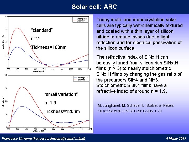
Solar cell: ARC “standard” n=2 Tickness=100 nm “small variation” n=1. 9 Tickness=120 nm Francesco Simeone (francesco. simeone@roma 1. infn. it) Today multi- and monocrystaline solar cells are typically wet-chemically textured and coated with a thin layer of silicon nitride to reduce losses due to light reflection and for electrical passivation of the silicon surface. The refractive index of Si. Nx: H can be easily tuned from silicon rich Si. Nx: H films (n > 3) to nearly stoichiometric Si. Nx: H films by changing the gas ratio of the precursors Si. H 4 and NH 3. Stoichiometric Si 3 N 4 films have a refractive index of around n = 1. 9. M. Junghänel, M. Schädel, L. Stolze, S. Peters 10. 4229/25 th. EUPVSEC 2010 -2 DV. 1. 70 9 Marzo 2015
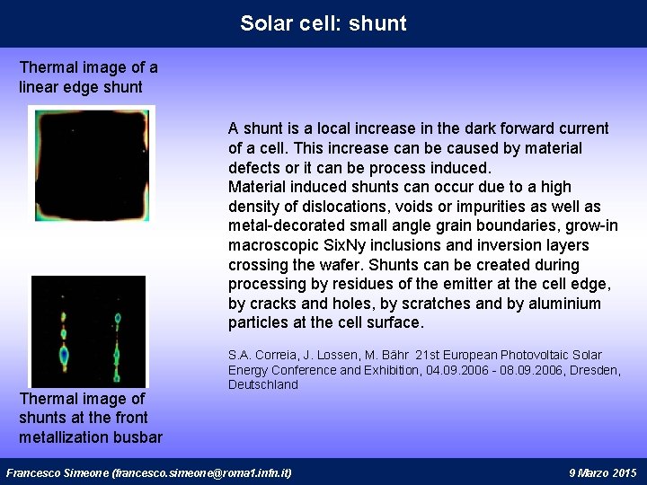
Solar cell: shunt Thermal image of a linear edge shunt A shunt is a local increase in the dark forward current of a cell. This increase can be caused by material defects or it can be process induced. Material induced shunts can occur due to a high density of dislocations, voids or impurities as well as metal-decorated small angle grain boundaries, grow-in macroscopic Six. Ny inclusions and inversion layers crossing the wafer. Shunts can be created during processing by residues of the emitter at the cell edge, by cracks and holes, by scratches and by aluminium particles at the cell surface. Thermal image of shunts at the front metallization busbar S. A. Correia, J. Lossen, M. Bähr 21 st European Photovoltaic Solar Energy Conference and Exhibition, 04. 09. 2006 - 08. 09. 2006, Dresden, Deutschland Francesco Simeone (francesco. simeone@roma 1. infn. it) 9 Marzo 2015
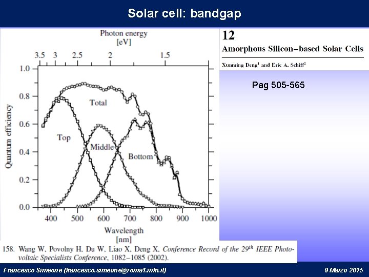
Solar cell: bandgap Pag 505 -565 Francesco Simeone (francesco. simeone@roma 1. infn. it) 9 Marzo 2015
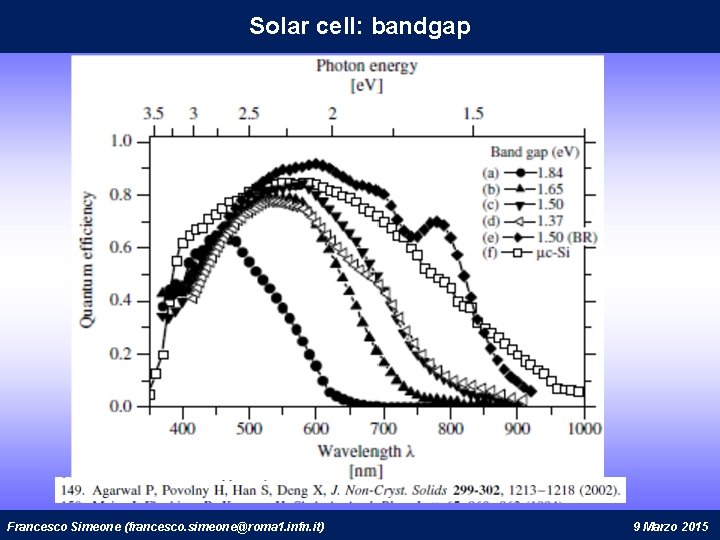
Solar cell: bandgap Francesco Simeone (francesco. simeone@roma 1. infn. it) 9 Marzo 2015
Francesco Simeone (francesco. simeone@roma 1. infn. it) 9 Marzo 2015
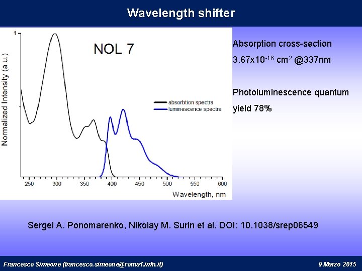
Wavelength shifter Absorption cross-section 3. 67 x 10 -16 cm 2 @337 nm Photoluminescence quantum yield 78% Sergei A. Ponomarenko, Nikolay M. Surin et al. DOI: 10. 1038/srep 06549 Francesco Simeone (francesco. simeone@roma 1. infn. it) 9 Marzo 2015