The Henryk Niewodniczaski Institute of Nuclear Physics Polish


- Slides: 15

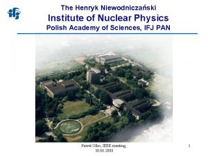
The Henryk Niewodniczański Institute of Nuclear Physics Polish Academy of Sciences • The Institute of Nuclear Physics was established in Cracow in 1955. Currently IFJ PAN is the largest research institute of the Polish Academy of Sciences. • The Institute employs of over 550 people. • The average yearly yield of the IFJ PAN in recent years encompasses more than 500 scientific papers in the Journal Citation Reports published by the Thomson Reuters. • The Institute is of A+ Category (leading level in Poland) in the field of sciences and engineering. Cooperation with: BNL – Brookhaven, CERN – Geneva, DESY – Hamburg, ENEA – Frascati, GANIL – Caen, GSI – Darmstadt, ILL – Grenoble, JINR – Dubna, KEK – Tsukuba, KFZ – Juelich, LNGS – Gran Sasso, LNL – Legnaro, MIT – Cambridge, MPI – Greifswald.

The Henryk Niewodniczański Institute of Nuclear Physics Polish Academy of Sciences • Scientific divisions • • • Division of Particle and Astroparticle Physics Division of Nuclear Physics and Strong Interactions Division of Condensed Matter Physics Division of Theoretical Physics Division of Interdisciplinary Research Division of Applications of Physics • Accredited laboratories • • Laboratory of Individual and Environmental Dosimetry Laboratory of Radiometric Expertise Laboratory of Radioactivity Analyses Laboratory for Calibration of Radiation Protection Instruments • Cyclotron Center Bronowice (CCB) • • Radiotherapy of central nervous system tumours Eye melanoma radiotherapy facility • Krakow Research Center for Ion Engineering (IONMED) • Division of Scientific Equipment and Infrastructure Construction (DAI)

Division of Scientific Equipment and Infrastructure Construction (DAI) ESS LUND E-XFEL DESY W 7 X IPP GREIFSWALD SPIRAL 2 GANIL T 2 K, J-PARC BELLE 2, KEK IFJ PAN KRAKÓW CTA CHILE FAIR DARMSTAT LHC, ATLAS CERN ITER CADARACHE DONES F 4 E BARCELONA

Division of Scientific Equipment and Infrastructure Construction (DAI) Telescope CTA mirror COMPASS-U tokamak Central solenoid of the COMPASS-U tokamak Telescope CTA (small) DONES – Start-up and Monitoring Module (STUMM) Canted-Cosine-Theta magnet ATLAS – cooling system for the electronics

2 D Model of CCT Magnet with Four Layers Jacek Błocki, Rafał Ortwein, Przemysław Wąchal Institute of Nuclear Physics Polish Academy of Sciences Krakow, Poland 29/10/2019 CERN

To analyze CCT magnet we had the following input data: 1. CAD model 2. File „forcedensity. txt” – EM force densities [N/m 3] 3. CCT 1. gmsh files - using Gsmh. exe we transfer these files to CCT 1_coil 1. inp (ANSYS) and then force densities [N/m 3] to normal forces [N] Coil I

Fx Fz Fy Z Z Z EM force and moment (torque) distributions along the Coil I axis (Z direction) Mz COIL I Rmin = 75 mm, Rmin(coil) = 79 mm, Rmax(coil) = 84 mm, Rmax(composite) = 84. 3 mm. Z

Distribution of EM forces along the circumferential Fx/m theta (360/120) Fr/m tetha Fy/m tetha Fcircum. /m tetha Coil I Fz/m tetha Mz/m tetha

Cylinder III SUM OF F and M Fx = 6211 N, Fx = -5051 N, Fx = 3602 N, Fx = -4249 N, Fy = 8291 N, Fy = -8548 N, Fy = 5801 N, Fy = -5484 N, Fz = -38 N, Fz = 27 N, Fz = 12 N, Mz = 62023 Nm, Fz = -28 N, Mz = 77143 Nm, Mz = -67263 Nm, Cylinder IV Mz = -71799 Nm, SUM of EM Forces and Moment FOR ALL CYLINDERS Fx = 513 N Fy = 61 N, Fz = -82 N, Mz = 104 Nm. Mz between CYLINDER I and CYLINDER II = 62023 Nm, This torque causes the average shear stress between CYL I and CYL II, Mz between CYLINDER II and CYLINDER III = 139170 Nm, This torque causes the average shear stress between CYL II and CYL III, τ = 1. 02 MPa. τ = 1. 86 MPa. Mz between CYLINDER III and CYLINDER IV = -71800 Nm, This torque causes the average shear stress between CYL III and CYL IV, τ = Mz/(A R), A = 2 π R L, the cylinder length, R – the outer cylinder radius. τ = 0. 79 MPa.

2 D model ANSYS ELEM - PLANE 183 Generalized Plane Strain Option Isotropic material of AL. MAT 1 Orthotropic composite material MAT 3: Glass fiber - S 2, epoxy, 0. 3 mm thick Material properties of the layer MAT 2: Version 1: Version 2: Isotropic material of AL. Orthotropic material of Nb. Ti/Cu/epoxy This model cannot take into account EM forces in the axial directions (Z)

Version 1: Material Properties AL. MAT 1: E = 70 GPa, ni = 0. 33, TE = 13. 5 e-6 m/m/K P. Duthil, Material Properties at Low Temperature, Institut de Physique Nucléaire d’Orsay, IN 2 P 3 CNRS/Université de Paris Sud, Orsay, France E. D. Marquardt, J. P. Le, and Ray Radebaugh, Cryogenic Material Properties Database, 11 th International Cryocooler Conference, June 20 -22, 2000, Keystone, Co Orthotropic Composite MAT 3 - Glass fibre/epoxy: Ex = 24 GPa, Ey = 37 GPa, Ez = 35 GPa Gxy = 9. 7 GPa, Gxz = 8. 2 GPa, Gyz = 11. 6 GPa, nixy = 0. 11, niyz = 0. 27, nixz = 0. 42 TEx = 20. 9 e-6 m/m/K, TEy = TEz = 6. 8 e-6 m/m/K Composite Technology Development, Inc. – CTD-101 K

Version 2: Material Properties Orthotropic Composite MAT 2 – cable/epoxy The representative volume element (RVE) H. M. Ledbetter, D. T. Read, Orthorhombic elastic constants of an Nb. Ti/Cu composite superconductor, J. Appl. Physics, vol. 48, No. 5, May 1977 Orthotropic Composite MAT 2 – cable/epoxy (homogenized by means of a strain-energy): Ex = 15. 2 GPa, Ey = 15. 2 GPa, Ez = 64. 7 GPa Gxy = 12. 1 GPa, Gxz = 19. 3 GPa, Gyz = 19. 3 GPa, nixy = 0. 347, nixz = 0. 086, niyz = 0. 086, TEx = TEy = 23. 5 e-6 m/m/K, TEz = 7. 13 e-6 m/m/K

4 steps of loading 1. Elements of composite material MAT 3 are not active, Temperature is changing from 293 K to 416 K. 2. Elements of composite material MAT 3 are active, Temperature is changing from 416 K to 293 K. 3. Temperature is changing from 293 K to 4 k, 4. EM forces are applied.

Values of stresses in the MAT 3 (glass fibre/epoxy) for two different 2 D models and two versions of MAT 2 Version 1 for MAT 2 σ radial = (-6. 6 MPa, 6. 9 MPa) σ circum = (-151 Mpa, -128 Mpa) σz = (-145 Mpa, -139 Mpa) τ = (-10. 5 Mpa, 5. 8 Mpa) Version 2 for MAT 2 (-2. 0 MPa, 10. 8 MPa) (-161 Mpa, -128 Mpa) (-112 Mpa, -103 Mpa) (-9. 5 Mpa, 5. 1 Mpa)

2 D model ANSYS ELEM - PLANE 183 Plane Stress Option Orthotropic material of Nb. Ti/Cu/epoxy AL Glass fiber - S 2, epoxy, 0. 3 mm thick
 Petersburg nuclear physics institute
 Budker institute of nuclear physics
 Skobeltsyn institute of nuclear physics
 Budker
 Reverse polish notation adalah
 What is polish notation
 Lesson 15 nuclear quest nuclear reactions
 Fisión nuclear vs fision nuclear
 Nuclear safety institute of the russian academy of sciences
 Nuclear institute membership
 World nuclear transport institute
 Nuclear institute for agriculture and biology
 Nuclear physics
 Nuclear physics
 Shell model of nucleus
 Nuclear physics day
