Station Equipment RECEIVERS TRANSMITTERS TRANSCEIVERS MODULATION TRANVERTERS LOW


- Slides: 27
Station Equipment RECEIVERS, TRANSMITTERS, TRANSCEIVERS, MODULATION, TRANVERTERS, LOW POWER AND WEAK SIGNAL OPERATION, TRANSMIT AND RECEIVE AMPLIFIERS COMMON TRANSMITTER AND RECEIVER PROBLEMS BASIC REPAIR AND TESTING, USING BASIC TEST INSTRUMENTS
Individual topic �The color of the text is as follows: Black > is a introductory or further explanation statement Blue > is the question Red > is the answer (Bold) Brown > is the sub-element section and question number �See the next slides for examples
Receivers Transmitters In the early days of radio, amateur radio operators used separate receivers and transmitter units. Nowadays, however, most use radios called transceivers. A transceiver is a unit combining the functions of a transmitter and a receiver. (T 7 A 02)
Receivers Transmitters Often, HF transceivers are used with devices called transverters that convert the signals from their HF transceiver to the VHF, UHF, and even microwave bands. Transverters take the output of an HF transceiver, normally set to the 10 m (28 MHz) band output a VHF, UHF, or microwave signal. Conversely, they receive a VHF, UHF, or microwave signal and output a signal in the 10 m band that is demodulated by the HF transceiver. A device that converts the Rf input and output of a transceiver to another band is a transverter. (T 7 A 06)
Amplifiers One disadvantage of using a handheld transceiver is that the maximum output power is generally only 5 W, and because of this, they have limited range. To get around this limitation, you can use an RF amplifer to boost the power. To set the amplifier for properation in the selected mode use the SSB/CW-FM switch on a VHF power amplifier. (T 7 A 09)
Amplifiers Many, if not most, new amateurs buy a hand-held transceiver, usually called an “HT, ” as their first transceiver. One disadvantage of using a hand-held transceiver is that the maximum output power is generally only 5 W, and because of this, they have limited range. To increase the low-power output of a handheld transceiver, and therefore its range, you can use an RF power amplifier. (T 7 A 10)
Receivers Transmitters When talking about a transceiver’s specifications, we still refer to its receiver and transmitter. The two most important specifications for a receiver are sensitivity and selectivity. Sensitivity is the term that describes the ability of a receiver to detect the presence of a signal. (T 7 A 01) The term that describes the ability of a receiver to discriminate between multiple signals is selectivity. (T 7 A 04)
Receivers Transmitters To improve the sensitivity of a receiver, you can use an RF preamplifier. An RF preamplifier is installed between the antenna and receiver. (T 7 A 11)
Receivers Transmitters Most HF transceivers have some version of a superheterodyne receiver. In a super-heterodyne receiver, we first convert an incoming radio signal from its frequency to an intermediate frequency, or IF. The circuit that does this is the mixer. A mixer is used to convert a radio signal from one frequency to another. (T 7 A 03)
Receivers Transmitters When transmitting, we want to generate an RF signal with a specific frequency. To do that, we use an oscillator. Oscillator is the name of a circuit that generates a signal of a desired frequency. (T 7 A 05)
Receivers Transmitters To transmit a voice or data signal, we have to combine an audio frequency signal from the microphone with the RF carrier signal generated by the transmitter. Modulation is the term that describes combining speech with an RF carrier signal. (T 7 A 08) Modulators use a type of mixer circuit to accomplish this process.
Common Transmitter and Receiver Problems Since Murphy’s Law—the law that states if anything can go wrong, it will—applies to amateur radio as much as it does to any other pursuit, at some point you will have to deal with problems. These may include overload, distortion, feedback, and interference. Let’s first consider interference. All of these choices are correct when talking about causes of radio frequency interference (T 7 B 03): • fundamental overload • harmonics • spurious emissions
Common Transmitter and Receiver Problems Any of these could cause interference to a TV set or radio, and you will want to take steps to find and eliminate that interference. If someone tells you that your station’s transmissions are interfering with their radio or TV reception, you should first make sure that your station is functioning properly and that it does not cause interference to your own radio or television when it is tuned to the same channel or frequency. (T 7 B 06)
Common Transmitter and Receiver Problems While it’s not very likely that your amateur radio station will interfere with a neighbor’s cable TV service, it can sometimes occur. The first step to resolve cable TV interference from your ham radio transmission is to be sure all TV coaxial connectors are installed properly. (T 7 B 12)
Common Transmitter and Receiver Problems Your amateur radio station may interfere with a nearby radio receiver if your signal is so strong that the receiver cannot reject the signal even though your signal is not on the frequency to which the receiver is tuned. When a receiver is unable to reject strong signals outside the AM or FM band, it can cause a broadcast AM or FM radio to receive an amateur radio transmission unintentionally. (T 7 B 02) One way to reduce or eliminate the overloading of a nonamateur radio or TV receiver by an amateur signal is to block the amateur signal with a filter at the antenna input of the affected receiver. (T 7 B 05)
Common Transmitter and Receiver Problems Another device that often experiences interference from amateur radio stations is the telephone. The telephone wires act as antenna and the telephone itself demodulates the signal. One way to reduce or eliminate interference by an amateur transmitter to a nearby telephone is to put an RF filter on the telephone. (T 7 B 04)
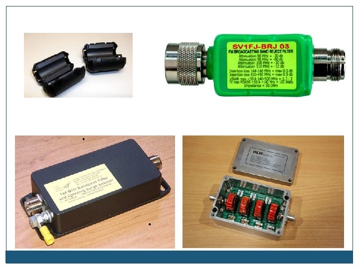
Common Transmitter and Receiver Problems A band-reject filter can reduce overload to a VHF transceiver from a nearby FM broadcast station? (T 7 B 07):
Common Transmitter and Receiver Problems Interference works both ways. Your neighbors may have wireless devices, sometimes called “Part 15 devices, ” that can interfere with your station. A Part 15 device is an unlicensed device that may emit low powered radio signals on frequencies used by a licensed service. (T 7 B 09) All of these choices are correct when considering what you should do if something in a neighbor’s home is causing harmful interference to your amateur station (T 7 B 08): • Work with your neighbor to identify the offending device • Politely inform your neighbor about the rules that require him to stop using the device if it causes interference • Check your station and make sure it meets the standards of good amateur practice
Common Transmitter and Receiver Problems Perhaps the most common problem that amateur radio operators have is distorted or noisy audio when transmitting. There are many reasons for poor audio. All of these choices are correct if you receive a report that your audio signal through the repeater is distorted or unintelligible (T 7 B 10): • Your transmitter may be slightly off frequency • Your batteries may be running low • You could be in a bad location
Common Transmitter and Receiver Problems Reports of garbled, distorted, or unintelligible transmissions is a symptom of RF feedback in a transmitter or transceiver. (T 7 B 11) Sometimes, garbled or distorted audio when operating FM is the result of over-deviation. Talk farther away from the microphone is one thing you can do if you are told your FM handheld or mobile transceiver is over-deviating. (T 7 B 01)
Basic repair and testing / Using test instruments The most common test instrument in an amateur radio shack is the multimeter. Multimeters combine into a single instrument the functions of a voltmeter, ohmmeter, and ammeter. Voltage and resistance are two measurements commonly made using a multimeter. (T 7 D 07)
Basic repair and testing / Using test instruments You use a voltmeter to measure electric potential or electromotive force. (T 7 D 01) The correct way to connect a voltmeter to a circuit is in parallel with the circuit. (T 7 D 02) When measuring high voltages with a voltmeter, one precaution you should take is to ensure that the voltmeter and leads are rated for use at the voltages to be measured. (T 7 D 12)
Basic repair and testing / Using test instruments An ohmmeter is the instrument used to measure resistance. (T 7 D 05) When measuring circuit resistance with an ohmmeter ensure that the circuit is not powered. (T 7 D 11) Attempting to measure voltage when using the resistance setting might damage a multimeter. (T 7 D 06) What is probably happening when an ohmmeter, connected across a circuit, initially indicates a low resistance and then shows increasing resistance with time is that the circuit contains a large capacitor. (T 7 D 10)
Basic repair and testing / Using test instruments An ammeter is the instrument used to measure electric current. (T 7 D 04) An ammeter is usually connected to a circuit in series with the circuit. (T 7 D 03)
Basic repair and testing / Using test instruments In addition to knowing how to make electrical measurements, knowing how to solder is an essential skill for amateur radio operators. Rosin-core solder is best for radio and electronic use. (T 7 D 08) A grainy or dull surface is the characteristic appearance of a “cold” solder joint. (T 7 D 09)
Cold Solder Joint