Shear Wave Velocity Profiling Using Simplified Equipment Sponsored




- Slides: 22
Shear Wave Velocity Profiling Using Simplified Equipment Sponsored by State Farm Insurance Shivan Haran, Ph. D. And Ashraf Elsayed, Ph. D. , P. E. Arkansas State University
PROJECT OBJECTIVES Ø Determine shear wave velocity profiles at several locations in Craighead County using simplified equipment Ø Evaluate liquefaction potential Ø Recommendations
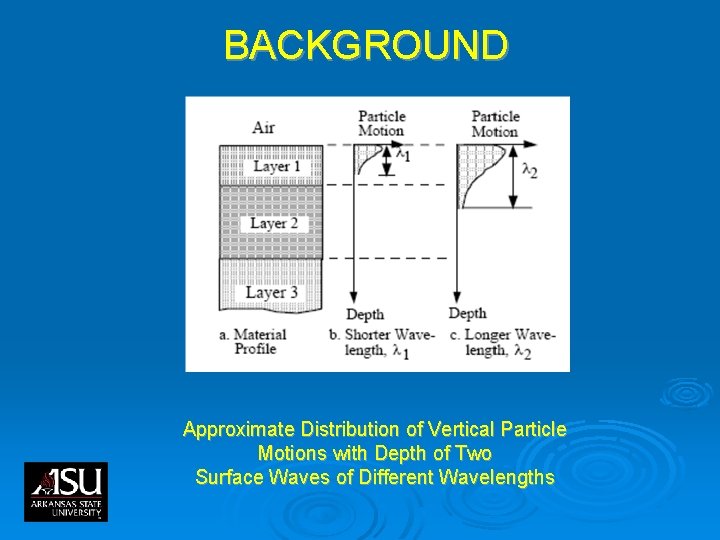
BACKGROUND Approximate Distribution of Vertical Particle Motions with Depth of Two Surface Waves of Different Wavelengths
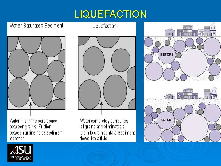
DEFINITIONS Ø Shear Wave Velocity l A property used to establish the stiffness of the soil in small strain Ø Liquefaction l A loss of strength and stiffness of loose saturated cohesion-less soil, resulting in bearing capacity loss, large lateral displacement, and seismic settlement of ground
LIQUEFACTION
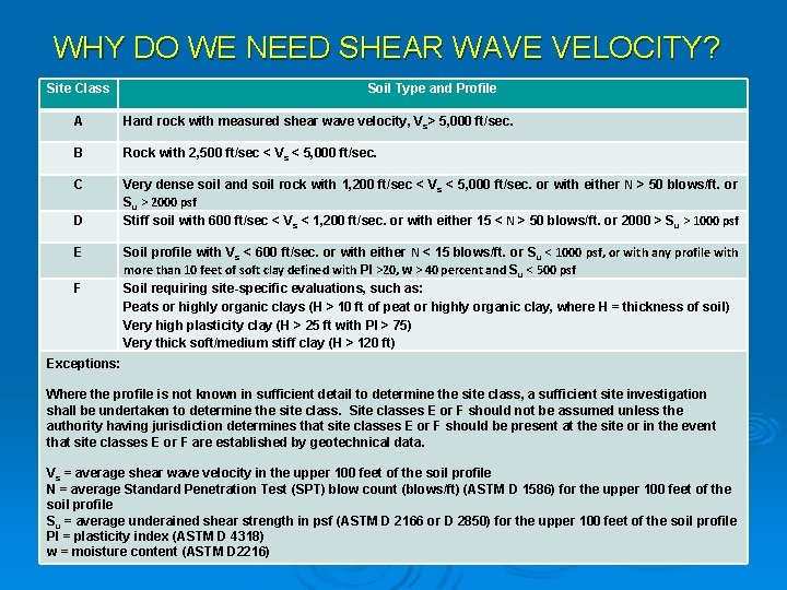
WHY DO WE NEED SHEAR WAVE VELOCITY? Site Class Soil Type and Profile A Hard rock with measured shear wave velocity, Vs> 5, 000 ft/sec. B Rock with 2, 500 ft/sec < Vs < 5, 000 ft/sec. C Very dense soil and soil rock with 1, 200 ft/sec < Vs < 5, 000 ft/sec. or with either N > 50 blows/ft. or Su > 2000 psf Stiff soil with 600 ft/sec < V s < 1, 200 ft/sec. or with either 15 < N > 50 blows/ft. or 2000 > S u > 1000 psf D E F Soil profile with Vs < 600 ft/sec. or with either N < 15 blows/ft. or Su < 1000 psf, or with any profile with more than 10 feet of soft clay defined with PI >20, w > 40 percent and Su < 500 psf Soil requiring site-specific evaluations, such as: Peats or highly organic clays (H > 10 ft of peat or highly organic clay, where H = thickness of soil) Very high plasticity clay (H > 25 ft with PI > 75) Very thick soft/medium stiff clay (H > 120 ft) Exceptions: Where the profile is not known in sufficient detail to determine the site class, a sufficient site investigation shall be undertaken to determine the site class. Site classes E or F should not be assumed unless the authority having jurisdiction determines that site classes E or F should be present at the site or in the event that site classes E or F are established by geotechnical data. Vs = average shear wave velocity in the upper 100 feet of the soil profile N = average Standard Penetration Test (SPT) blow count (blows/ft) (ASTM D 1586) for the upper 100 feet of the soil profile Su = average underained shear strength in psf (ASTM D 2166 or D 2850) for the upper 100 feet of the soil profile PI = plasticity index (ASTM D 4318) w = moisture content (ASTM D 2216)
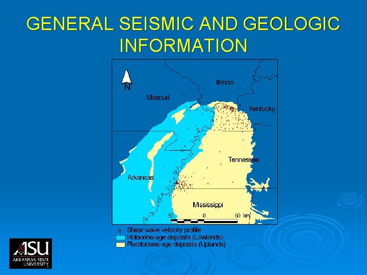
GENERAL SEISMIC AND GEOLOGIC INFORMATION
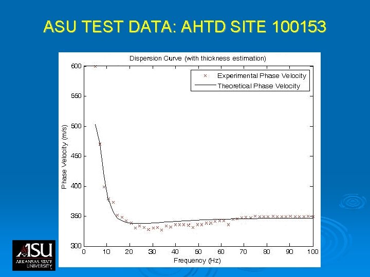
SASW TESTING § SASW testing consists of taking field measurements of surface wave phase velocity, VR, at numerous wavelengths, l. R, and using these measurements to calculate a dispersion curve for the site § A dispersion curve displays the variation in phase velocity with frequency 8
SASW TESTING Configuration of Equipment Used in SASW Testing with a Two-Channel System
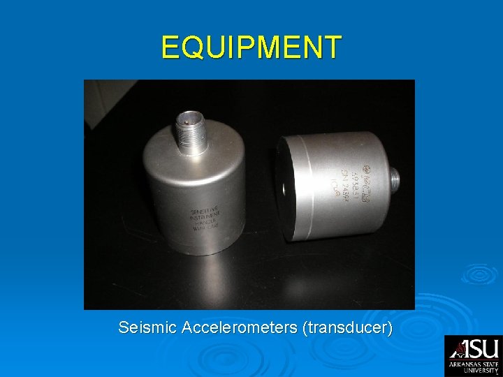
EQUIPMENT Seismic Accelerometers (transducer)
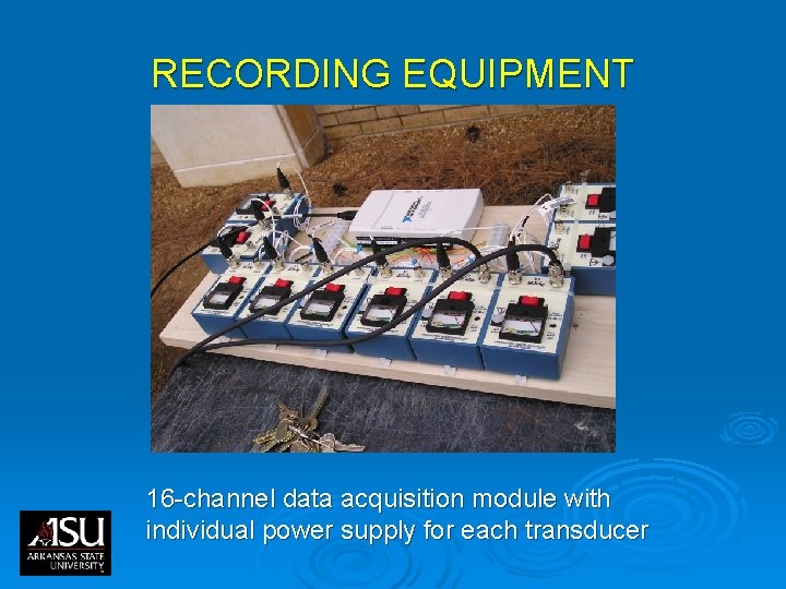
RECORDING EQUIPMENT 16 -channel data acquisition module with individual power supply for each transducer
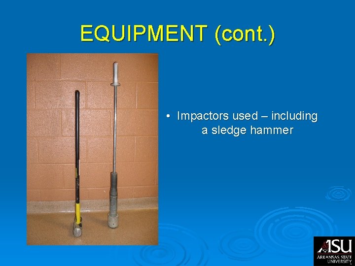
EQUIPMENT (cont. ) • Impactors used – including a sledge hammer
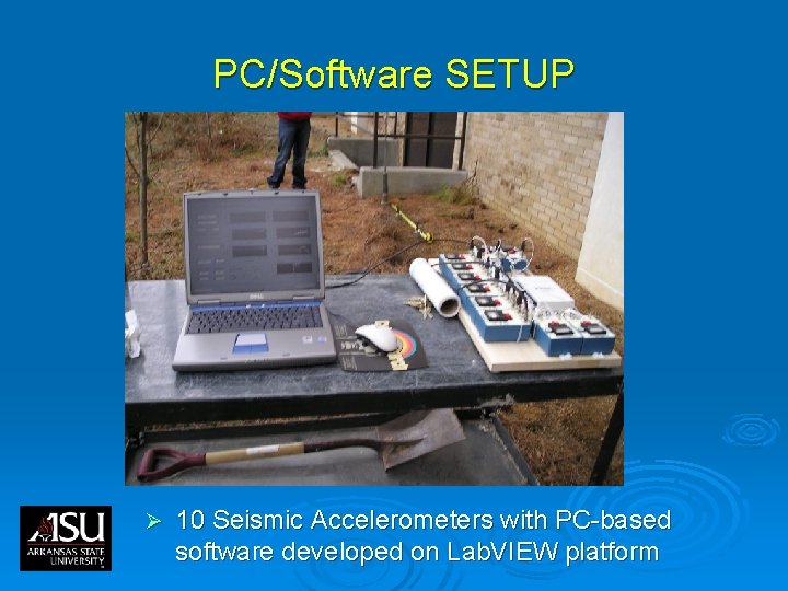
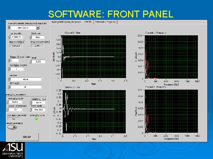
PC/Software SETUP Ø 10 Seismic Accelerometers with PC-based software developed on Lab. VIEW platform
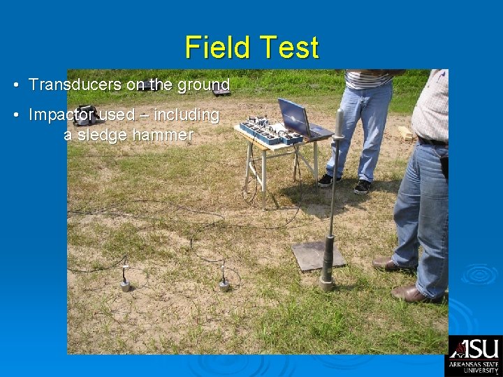
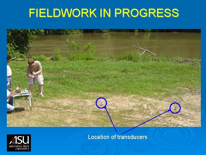
Field Test • Transducers on the ground • Impactor used – including a sledge hammer
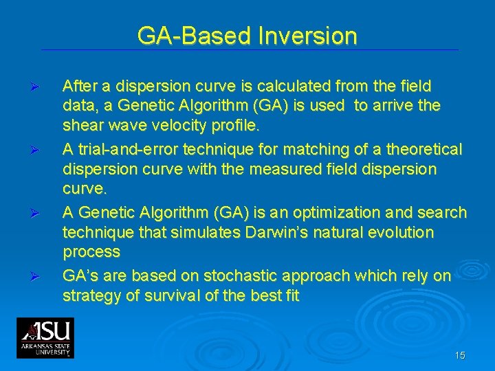
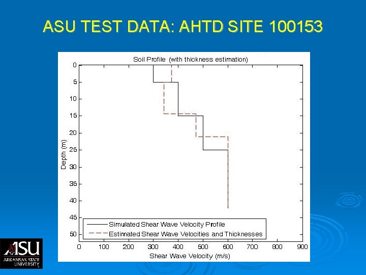
GA-Based Inversion Ø Ø After a dispersion curve is calculated from the field data, a Genetic Algorithm (GA) is used to arrive the shear wave velocity profile. A trial-and-error technique for matching of a theoretical dispersion curve with the measured field dispersion curve. A Genetic Algorithm (GA) is an optimization and search technique that simulates Darwin’s natural evolution process GA’s are based on stochastic approach which rely on strategy of survival of the best fit 15
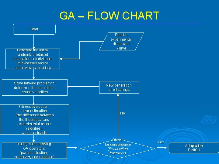
GA – FLOW CHART Start Generate the initial randomly produced population of individuals (thicknesses and/or shear-wave velocities) Solve forward problem to determine theoretical phase velocities Fitness evaluation, error estimation (the difference between theoretical and experimental phase velocities), and constraints Mating pool, applying GA operators (parent selection, crossover, and mutation) Read in experimental dispersion curve New generation of off springs No Check for convergence (E<specified tolerance) Yes Adaptation FINISH
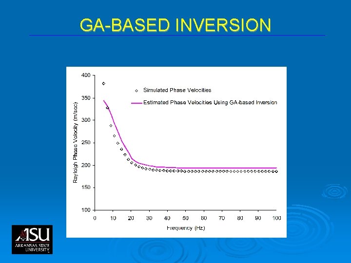
GA-BASED INVERSION
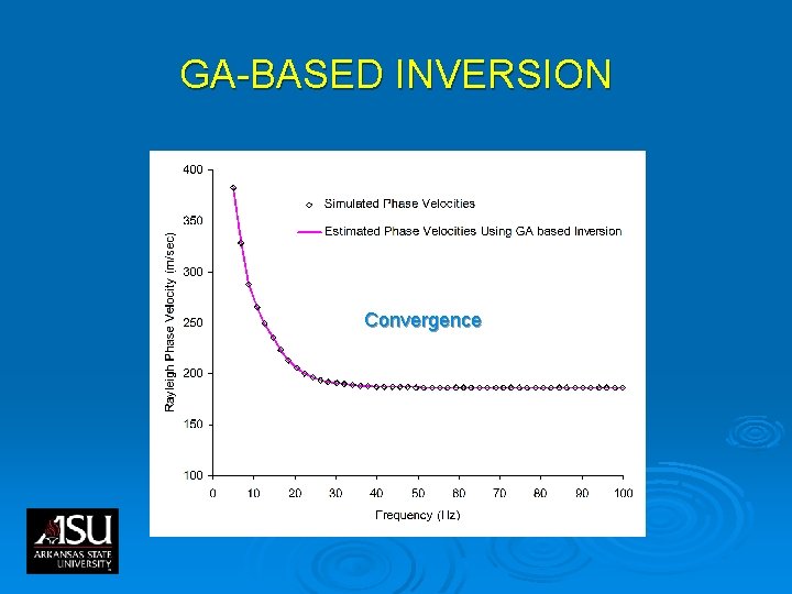
GA-BASED INVERSION Convergence
FIELDWORK IN PROGRESS Location of transducers
SOFTWARE: FRONT PANEL
ASU TEST DATA: AHTD SITE 100153
ASU TEST DATA: AHTD SITE 100153