ShackHartmann SH Sensors Wavefront Sensing Applications Astronomical Telescope


- Slides: 12

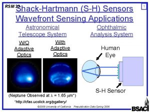
Shack-Hartmann (S-H) Sensors Wavefront Sensing Applications Astronomical Telescope System W/O Adaptive Optics Ophthalmic Analysis System With Adaptive Optics Human Eye (Neptune Observed at = 1. 65 m*) S-H Sensor *http: //cfao. ucolick. org/pgallery/ © 2005 University of California Prepublication Data Spring 2005 1

Conventional Shack-Hartmann Sensors Microlens Array CCD Camera Gap CCD Imager © 2005 University of California Prepublication Data Spring 2005 2

S-H Sensor Operating Principle Light travels in a direction perpendicular to the wavefront! Lens 3 Optical Axis Focal Point Wavefront Slope Optical Axis © 2005 University of California Prepublication Data Spring 2005

Incoming Wavefront S-H Sensor Operating Principle (Cont. ) * Side view 1 3 Front view (CCD) CCD 1 1 3 3 2 1 3 *J. M Geary, Wavefront Sensors, 1995 © 2005 University of California Prepublication Data Spring 2005 2 4 4 4

Dynamic Range and Sensitivity 5 Sub-aperture MAX Dynamic Range: MAX Sensitivity: MIN f MIN CCD f , MAX (worse), MIN (better) f , MAX (better), MIN (worse) © 2005 University of California Prepublication Data Spring 2005

Incoming Wavefront Shack-Hartmann Sensor Limitations Side view Largely Aberrate d Wavefro nt 1 3 Error! 1 Front view (CCD) 1 2 1 3 3 6 3 2 4 4 Focal point #3 is misplaced into subaperture 1! © 2005 University of California Prepublication Data Spring 2005

7 Incoming Wavefront Vibrating Microlens Side view 1 f. R 3 3 Front view (CCD) 1 1 f. R 3 3 2 1 3 3 2 4 4 Identify the microlens and its associated focal point by resonating the lens: focal point scanning line. © 2005 University of California Prepublication Data Spring 2005

MEMS Addressable Array: Concept Unit 2 f. R 1 f. R 2 f. R 3 f. R(N-1) f. RN GND Unit 1 VDC+VAC exp(j t) Unit 3 Unit(N-1) Unit. N VDC+VAC exp(j t+j /4) Make the mechanical unit (of interest) resonate by setting the frequency of the driving voltage equal to the unit’s resonant frequency. Pair of electrical interconnects per row/array © 2005 University of California Prepublication Data Spring 2005 8

SEM of MEMS Lens-Carriage Array Lens Carriage Comb Sets Flexures Nitride Membrane Flexures Drive Lines © 2005 University of California Prepublication Data Spring 2005 9

Microlens Fabrication Process Using Polymer-Jet Printing 10 Stroboscopic View of Micro. Jet-Dispenser Droplet Formatio 1 2 3 4 Stroboscopic View of Microlens Formation 1 2 © 2005 University of California 3 Prepublication Data Spring 2005 4

Addressable MEMS-Microlens Array 1500 m 800 m © 2005 University of California Prepublication Data Spring 2005 11

Individual Resonant Motions 12 • Expect improvements by a factor of 20 -40 over the ynamic range and sensitivity of conventional SH senso © 2005 University of California Prepublication Data Spring 2005
 What is angular magnification
 Astronomical applications department
 Em wave2
 Shack hartmann wavefront sensor tutorial
 Wavefront distributed tracing
 Austin roorda
 Wavefront
 Wavefront architecture
 Remote sensing applications center
 Remote sensing applications center
 Seasons diagram
 Guildford astronomical society
 Astronomical clock lyon france
