Sedimentation Downstream Processing Short Course May 2007 Kevin
- Slides: 16
Sedimentation Downstream Processing Short Course May 2007 Kevin Street Gavin Duffy
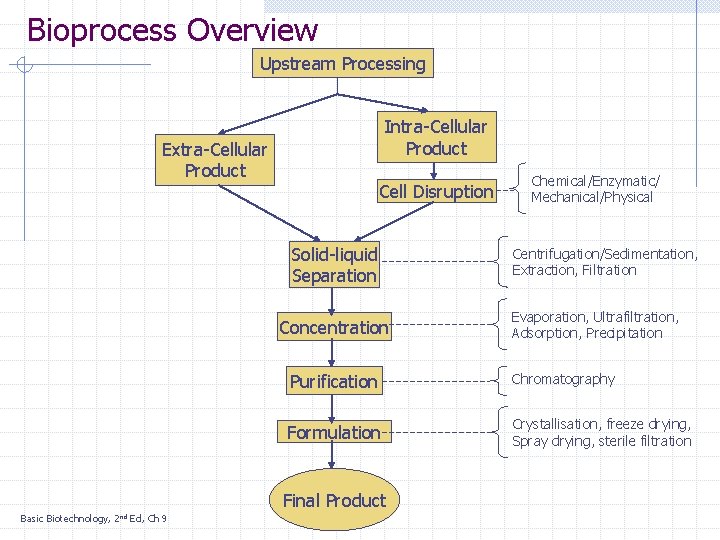
Bioprocess Overview Upstream Processing Intra-Cellular Product Extra-Cellular Product Cell Disruption Solid-liquid Separation Concentration Basic Biotechnology, Ed, Ch 9 Centrifugation/Sedimentation, Extraction, Filtration Evaporation, Ultrafiltration, Adsorption, Precipitation Purification Chromatography Formulation Crystallisation, freeze drying, Spray drying, sterile filtration Final Product 2 nd Chemical/Enzymatic/ Mechanical/Physical
Learning Outcomes After this lecture you should be able to… Describe the sedimentation process and equipment Describe the motion of particles in free fall Calculate the terminal velocity of a particle
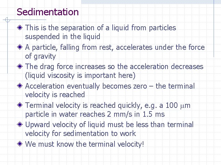
Sedimentation This is the separation of a liquid from particles suspended in the liquid A particle, falling from rest, accelerates under the force of gravity The drag force increases so the acceleration decreases (liquid viscosity is important here) Acceleration eventually becomes zero – the terminal velocity is reached Terminal velocity is reached quickly, e. g. a 100 m particle in water reaches 2 mm/s in 1. 5 ms Upward velocity of liquid must be less than terminal velocity for sedimentation to work We must know the terminal velocity!
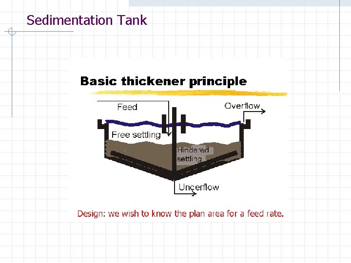
Sedimentation Tank
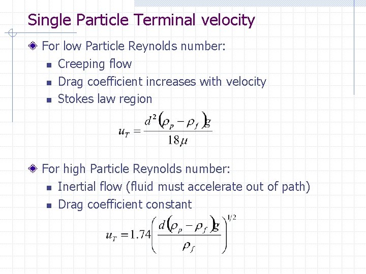
Single Particle Terminal velocity For low Particle Reynolds number: n Creeping flow n Drag coefficient increases with velocity n Stokes law region For high Particle Reynolds number: n Inertial flow (fluid must accelerate out of path) n Drag coefficient constant
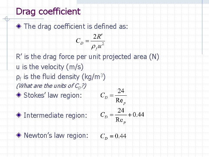
Drag coefficient The drag coefficient is defined as: R’ is the drag force per unit projected area (N) u is the velocity (m/s) ρf is the fluid density (kg/m 3) (What are the units of CD? ) Stokes’ law region: Intermediate region: Newton’s law region:
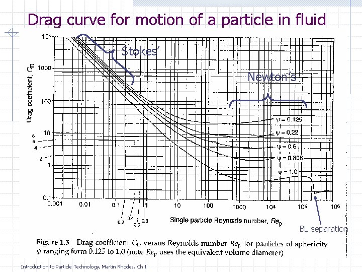
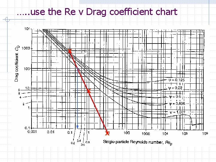
Drag curve for motion of a particle in fluid Stokes’ Newton’s BL separation Introduction to Particle Technology, Martin Rhodes, Ch 1
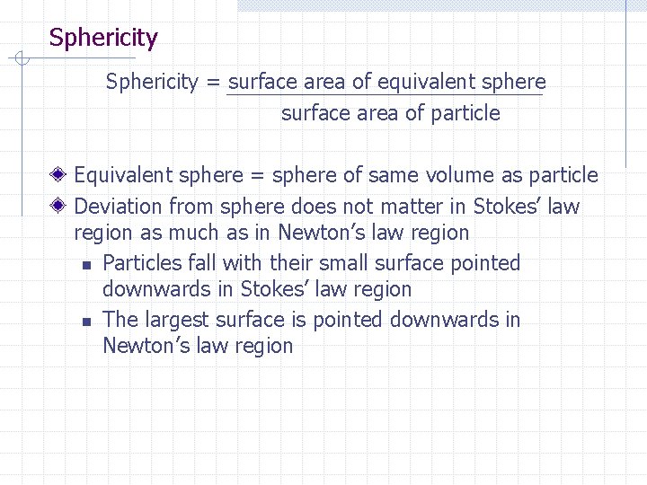
Sphericity = surface area of equivalent sphere surface area of particle Equivalent sphere = sphere of same volume as particle Deviation from sphere does not matter in Stokes’ law region as much as in Newton’s law region n Particles fall with their small surface pointed downwards in Stokes’ law region n The largest surface is pointed downwards in Newton’s law region
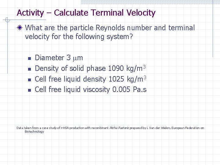
Activity – Calculate Terminal Velocity What are the particle Reynolds number and terminal velocity for the following system? n n Diameter 3 m Density of solid phase 1090 kg/m 3 Cell free liquid density 1025 kg/m 3 Cell free liquid viscosity 0. 005 Pa. s Data taken from a case study of r-HSA production with recombinant Pichia Pastoris prepared by L Van der Wielen, European Federation on Biotechnology
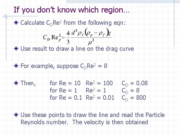
If you don’t know which region… Calculate CDRe 2 from the following eqn: Use result to draw a line on the drag curve For example, suppose CDRe 2 = 8 Then, for Re = 10 Re 2 = 100 for Re = 1 Re 2 = 1 for Re = 0. 1 Re 2 = 0. 01 CD = 0. 08 CD = 800 Use these points to draw the line and read the Particle Reynolds number. The velocity is then obtained
…. . use the Re v Drag coefficient chart x x x
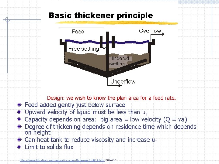
The Thickener Feed added gently just below surface Upward velocity of liquid must be less than u. T Capacity depends on area: big area = low velocity (Q = va) Degree of thickening depends on residence time which depends on height Can heat tank to reduce viscosity and increase u. T Limit to solids flux http: //www. filtration-and-separation. com/thickener/sld 004. htm 20/4/07
Batch Settling Test
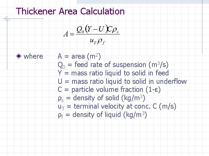
Thickener Area Calculation where A = area (m 2) Q 0 = feed rate of suspension (m 3/s) Y = mass ratio liquid to solid in feed U = mass ratio liquid to solid in underflow C = particle volume fraction (1 -ε) ρs = density of solid (kg/m 3) u. T = terminal velocity at conc. C (m/s) ρf = density of liquid (kg/m 3)
Activity – Calculate Terminal Velocity based on worked example 2. 1 from Rhodes.