SEDIMENTATION TANK Abdul Haqi Ibrahim Ph D Water
 School of Environmental")
SEDIMENTATION TANK Abdul Haqi Ibrahim, Ph. D Water Research Group (WAREG) School of Environmental Engineering Universiti Malaysia Perlis.

SEDIMENTATION • Typical sedimentation tanks used in water treatment are listed in Table 10 -1.
 a rectangular tank containing")
• preference for settling coagulation/flocculation floc is • (1) a rectangular tank containing high-rate settler modules, • (2) a long rectangular tank, and • (3) a high-speed microsand clarifier

rectangular sedimentation basin • Current design practice is shifting from rectangular sedimentation basins to high-rate settler modules or, in some cases, dissolved air flotation (DAF). • The rectangular sedimentation basin been the most frequently design

• To provide redundancy, two basins are placed longitudinally with a common wall.

SEDIMENTATION BASIN DESIGN-RECTANGULAR BASIN • 4 zone must be present • 1. inlet zone • 2. settling zone • 3. sludge zone • 4. outlet zone

INLET ZONE • preferred arrangement is a direct connection between the flocculation basin and the settling tank. • Disperse influent flow and suspended matter uniformly over the cross section of the basin • When the flocculated water must be piped to the settling tank, the flow velocity commonly used is in the range of 0. 15 to 0. 6 m/s. • This velocity must be reduced and the flow spread evenly over the cross section of the settling tank. • A diffuser wall is the most effective way to accomplish this.

SETTLING ZONE • Overflow rate is the primary design parameter for sizing the sedimentation basin

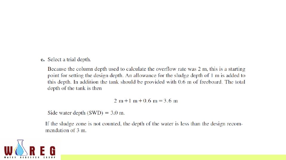
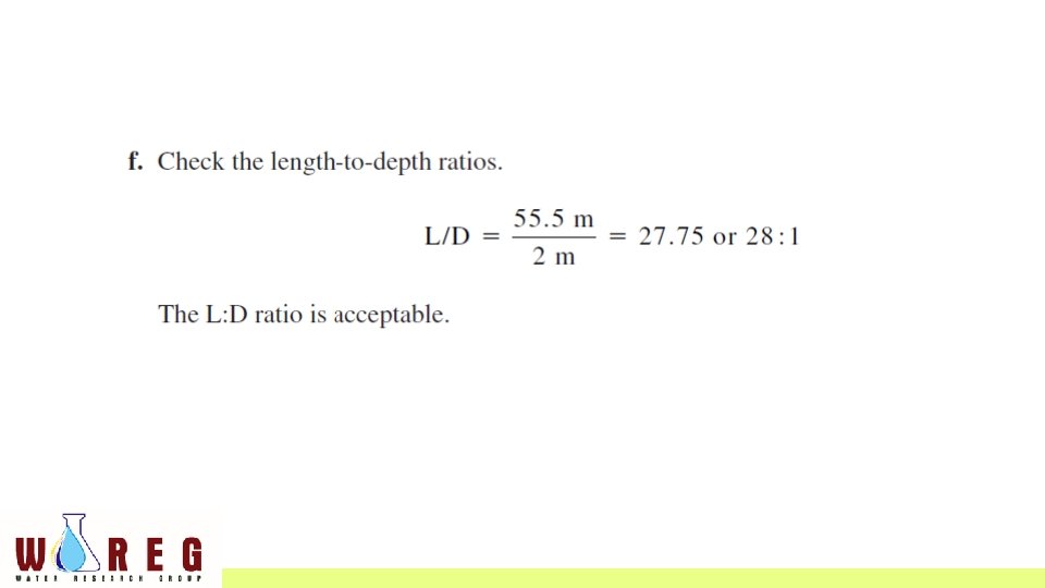
• These rates are usually conservative enough that the inlet zone does not have to be added to the length calculated for the settling zone • In theory the sedimentation basin depth [also called side water depth (SWD)] should not be a design parameter because removal efficiency is based on overflow rate. • However, there is a practical minimum depth required for sludge removal equipment • Open sedimentation tanks greater than 30 m in length are especially susceptible to wind effects • For longer tanks, wave breakers (launders or baffles) placed at 30 m intervals are recommended

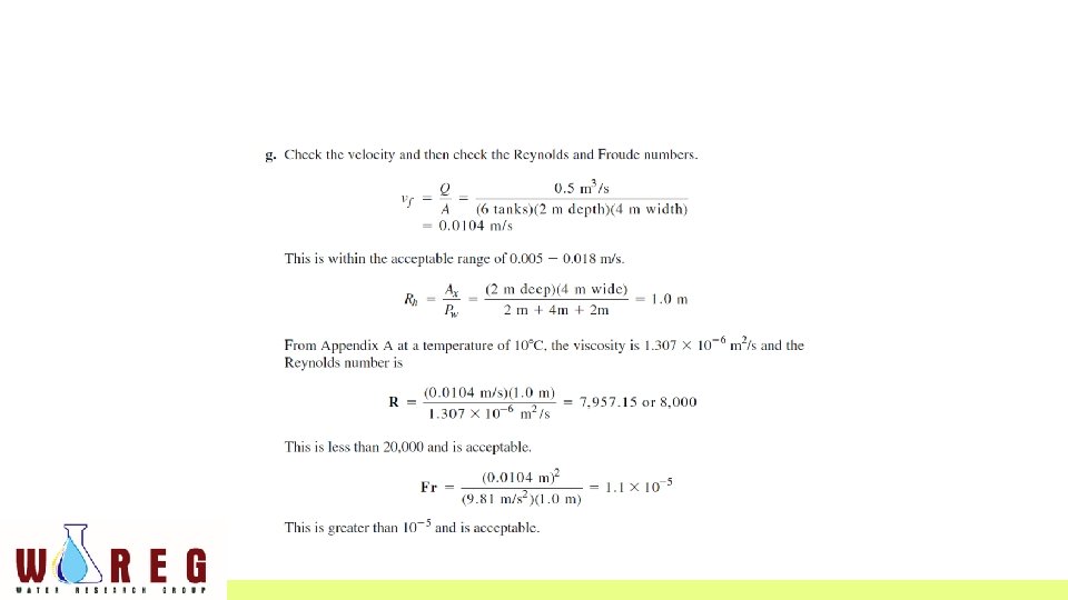
• The tank depth is usually increased by about 0. 6 m to provide freeboard to act as a wind barrier. • Horizontal flow velocities must be controlled to avoid undue turbulence, back mixing, and scour of particles from the sludge. • Reynolds and Froude numbers can be used to check on turbulence and back mixing.

The Reynolds number is determined as:

The Froude number is determined as:

• Recommended values for the settling zone design are R < 20, 000 and Fr > 10 -5 • large Reynolds number indicates a high degree of turbulence • A low Froude number indicates that water flow is not dominated by horizontal flow, and back mixing may occur.

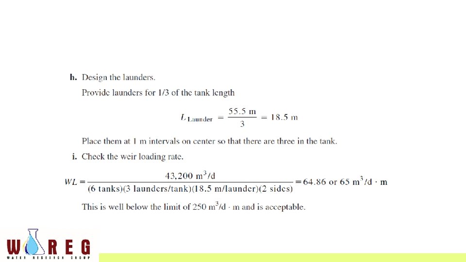
OUTLET ZONE • The outlet zone is composed of launders running parallel to the length of the tank • The weirs should cover at least one-third, and preferably up to one-half, the basin length • The water level in the tank is controlled by the end wall or overflow weirs.

SLUDGE ZONE • In selecting the depth of the sedimentation tank, an allowance of between 0. 6 and 1 m is made for sludge accumulation and sludge removal equipment. • To facilitate sludge removal, the bottom of the tank is sloped toward a sludge hopper at the head end of the tank • When mechanical equipment is used, the slope should be at least 1: 600

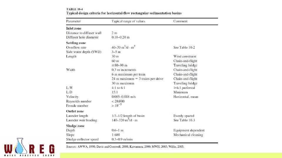
• Typical design criteria for horizontal-flow rectangular sedimentation basins in larger water treatment plants (40, 000 m 3 /d) are summarized in Table 10 -4. • Some design criteria are quite rigid while others only provide guidance.
 for the city of Stillwater’s water treatment plant")
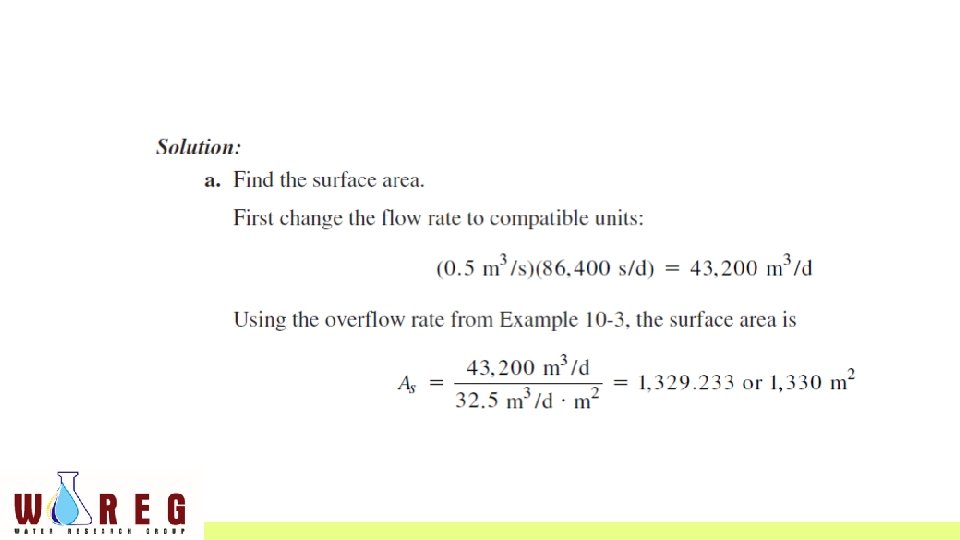
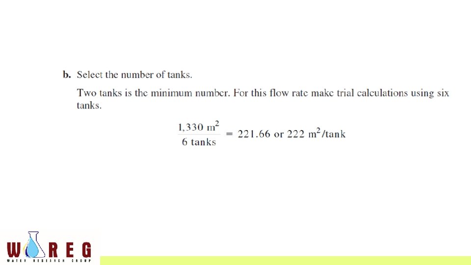
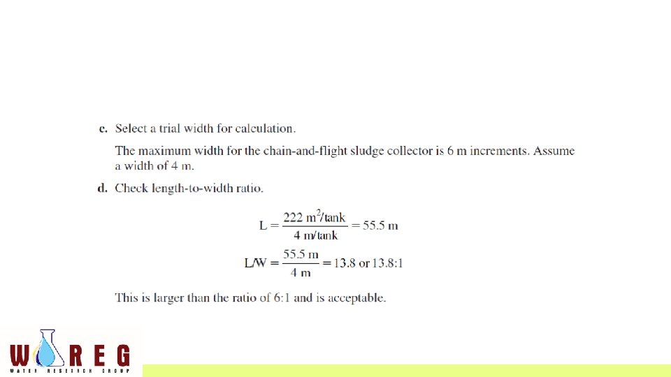
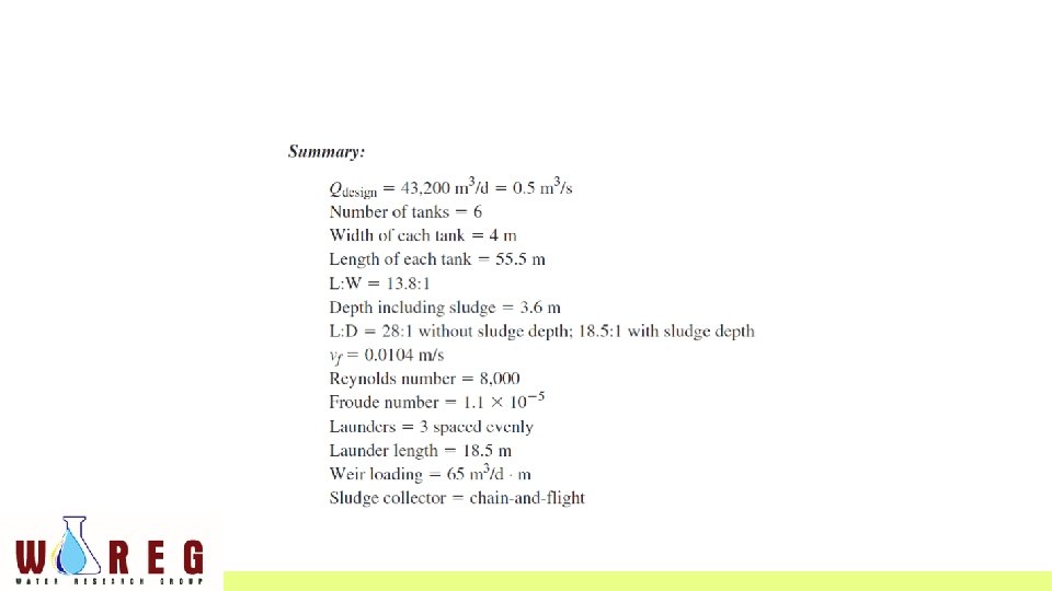
EXAMPLE • Design the settling tank(s) for the city of Stillwater’s water treatment plant expansion using the design overflow rate found in Example 10 -3. The maximum day design flow is 0. 5 m 3 /s. Assume a water temperature of 10 C.

The suggested design criteria in Table 10 -5 may be used for flow rates less than 40, 000 m 3 /d.

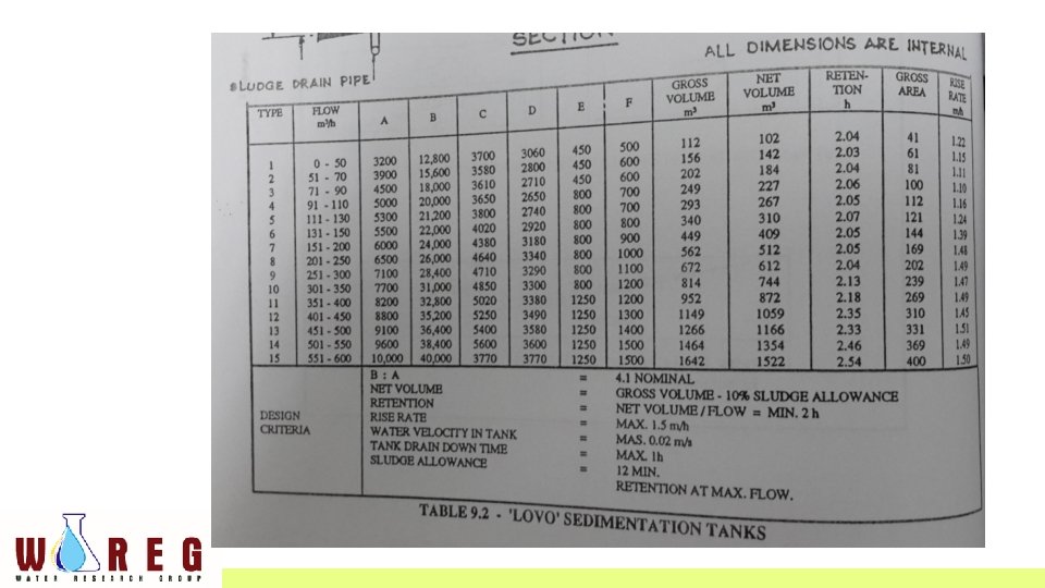
“LOVO TANK” • Modification of rectangular horizontal flow sedimentation tank • Incorporating an intermediate slanting slab spanning the whole width of the tank • Thus dividing it into a top and a bottom compartment.
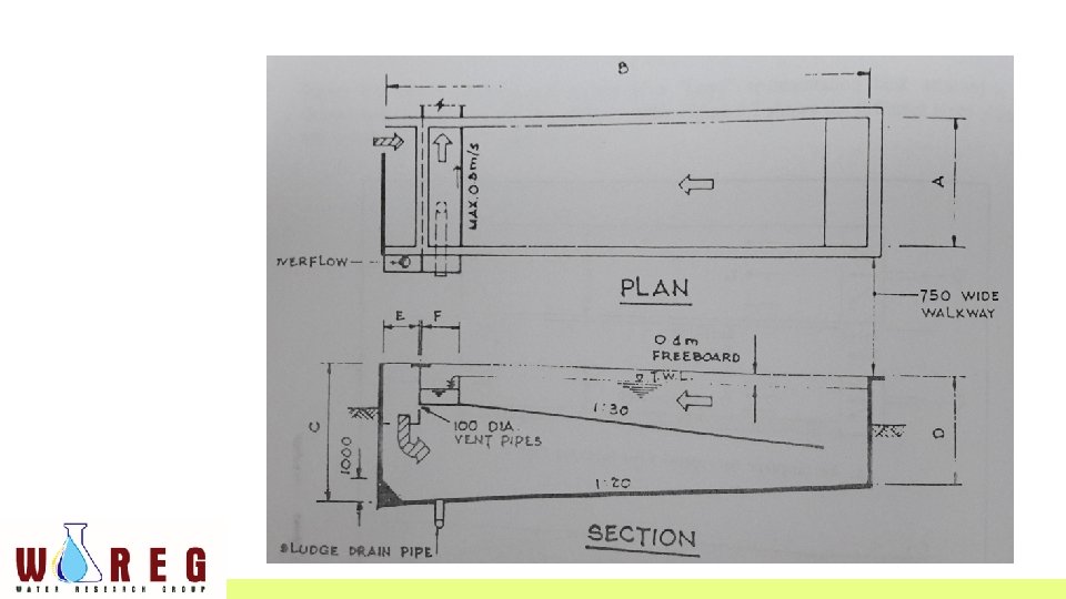

Design criteria for “LOVO” sedimentation tank • Surface loading @ overflow rate should not exceed 1. 5 m 3/m 2/hr • Detention time must not be less than 2 hrs • L: W is between 2: 1 and 4: 1 • Depth between 3 to 5 m • A certain quantity of sludge acculumation (10 to 15 % of tank capacity) should be allowed for in computing the capacity of the tank. • Inlet velocity should be in the region of 0. 1 m/sec and outlet weir loading should be about 8 m 3/hr/m
- Slides: 31