Section 3 Multiple Access Techniques MULTIPLE ACCESS TECHNIQES

 2. Time Division Multiple Access")
 In FDMA, the available mobile bandwidth is divided into")
 In TDMA, the transmission time is divided into portions")
 In CDMA systems, each user is identified by an")


 H EIR other BSSs A-bis A BTS Um BSC")


- Slides: 12
Section 3 Multiple Access Techniques
MULTIPLE ACCESS TECHNIQES 1. Frequency Division Multiple Access (FDMA) 2. Time Division Multiple Access (TDMA) 3. Code Division Multiple Access (CDMA)
FREQUENCY DIVISION MULTIPLE ACCESS (FDMA) In FDMA, the available mobile bandwidth is divided into portions of non-overlapping frequency slots which are assigned exclusively to individual users. Examples of this technique are TACS and AMPS cellular mobile systems.
TIME DIVISION MULTIPLE ACCESS (TDME) In TDMA, the transmission time is divided into portions of non-overlapping time slots, each assigned to each user in which they transmit. They have exclusive use of the entire bandwidth and communicate with each other by means of burst of signals. These time slots are grouped into a periodic structure called frame. Frame User 1 User 2 User 3 t burst e. g. GSM cellular mobile system
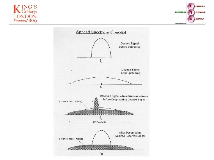
CODE DIVISION MULTIPLE ACCESS (CDMA) In CDMA systems, each user is identified by an address code (PN sequence) imposed on its carrier. Each user, uses the entire bandwidth and transmits whenever desired. No bandwidth or time sharing is required in CDMA. Signal identification is achieved at a receiving terminal by recognizing the corresponding address code.
DS – CDMA Systems Code Generator Chip rate Code Sync. Code Generator
Capacity for TDMA and FDMA Cellular Mobile Communications Number of Channels/Cell Total bandwidth Channel bandwidth or equivalent channel bandwidth Total no. of channels or equivalent channels Minimum required Carrier-to-Interference ratio per channel or per time slot No. of cells per cluster
AUC Base Station Subsystem (BSS) H EIR other BSSs A-bis A BTS Um BSC D G HLR F BTS other VLRs C VLR OMC B Mobile Services Switching Centre (MSC) BTS E MS Basic Architecture of GSM PSTN ISDN CSPDN PSPDN other MSCs BTS: BSC: HLR: VLR: OMC: EIR: AUC: Base Transceiver Station Base Station Controller Home Location Register Visited Location Register Operation & Maintenance Centre Equipment Identity Register Authentication Centre
Cells Based on a Hexagonal Grid. G . F . B A. . E Cell 1 MEAN RE-USE . C . G. F DISTAN CE . D. G . B. A Cell 8 . D. B
Capacity for CDMA System Bit energy psd of interference Total bandwidth Bit rate Number of channels/cell = Interference increase factor = 2/3 ( The contribution of all neighbour cells is equal to approximately Half the interference due to the mobiles within the cell)
* With the use of voice activity and antenna sectorization M Voice activity factor Ns = No. of sectors ( Reference IEEE Trans. On vehicular Technology vol. 4, No. 2, May 1991. )