PHY 2054 Physics II PHY 2054 Physics II


 – 1Ω=1 V/A • Resistance")


- Slides: 32
PHY 2054: Physics II
PHY 2054: Physics II • Calculate the Electric Field at P • Calculate the el. potential at P
PHY 2054: Physics II • Point charge • Distribution of charges • Line charge at an edge • Disc on an axis through the center
PHY 2054: Class Quiz If 500 J of work are required to carry a charged particle between two points with a potential difference of 20 V, the magnitude of the charge on the particle is: A. 0. 040 C B. 12. 5 C C. 20 C D. cannot be computed unless the path is given E. 25 C
Some old business: What is the electric field of a shell of a uniform spherical charge distribution? What is the potential for each of the above?
PHY 2054: Physics II E R V V r • Some old business The potential of a uniform spherical charge. • Calculate electric field, integrate it to get the potential
Two particles with charges Q and -Q are fixed at the vertices of an equilateral triangle with sides of length a. The work required to move a particle with charge q from the other vertex to the center of the line joining the fixed particles is: A. 0 B. k. Qq/a C. k. Qq/a 2 D. 2 k. Qq/a E. 1. 4 k. Qq/a
PHY 2054: Physics II • • • a= 39 cm q 1 = 3. 4 p. C q 2 = 6 p. C E at the center? What is the potential at the center?
Chapter 17 Current and Resistance
Electric Current • The current is the rate at which the charge flows through a surface – Look at the charges flowing perpendicularly through a surface of area A • The SI unit of current is Ampere (A) – 1 A = 1 C/s
Instantaneous Current • The instantaneous current is the limit of the average current as the time interval goes to zero: • If there is a steady current, the average and instantaneous currents will be the same
Electric Current, cont • The direction of the current is the direction positive charge would flow – This is known as conventional current direction • In a common conductor, such as copper, the current is due to the motion of the negatively charged electrons which move in the opposite direction. • It is common to refer to a moving charge as a mobile charge carrier – A charge carrier can be positive or negative
Current and Drift Speed • Charged particles move through a conductor of cross-sectional area A • n is the number of charge carriers per unit volume • n A Δx is the total number of charge carriers in the cylinder.
Current and Drift Speed, cont • The total charge is the number of carriers times the charge per carrier, q – ΔQ = (n A Δx) q • The drift speed, vd, is the speed at which the carriers move – vd = Δx/ Δt • Rewritten: ΔQ = (n A vd Δt) q • Finally, current, I = ΔQ/Δt = nqvd. A
Current and Drift Speed, final • If the conductor is isolated, the electrons undergo random motion • When an electric field is set up in the conductor, it creates an electric force on the electrons and hence a current
Charge Carrier Motion in a Conductor • The zig-zag black line represents the motion of a charge carrier in a conductor – The net drift speed is small • The sharp changes in direction are due to collisions • The net motion of electrons is opposite the direction of the electric field
Electrons in a Circuit • Assume you close a switch to turn on a light • The electrons do not travel from the switch to the bulb • The electrons already in the bulb move in response to the electric field set up in the completed circuit • A battery in a circuit supplies energy (not charges) to the circuit
Electrons in a Circuit, cont • The drift speed is much smaller than the average speed between collisions • When a circuit is completed, the electric field travels with a speed close to the speed of light • Although the drift speed is on the order of 10 -4 m/s, the effect of the electric field is felt on the order of 108 m/s
Circuits • A circuit is a closed path of some sort around which current circulates • A circuit diagram can be used to represent the circuit • Quantities of interest are generally current and potential difference
Meters in a Circuit – Ammeter • An ammeter is used to measure current – In line with the bulb, all the charge passing through the bulb also must pass through the meter
Meters in a Circuit – Voltmeter • A voltmeter is used to measure voltage (potential difference) – Connects to the two contacts of the bulb
Resistance • In a conductor, the voltage applied across the ends of the conductor is proportional to the current through the conductor • The constant of proportionality is the resistance of the conductor
Resistance, cont • Units of resistance are ohms (Ω) – 1Ω=1 V/A • Resistance in a circuit arises due to collisions between the electrons carrying the current with the fixed atoms inside the conductor
Georg Simon Ohm • 1787 – 1854 • Formulated the concept of resistance • Discovered the proportionality between current and voltages
Ohm’s Law • Experiments show that for many materials, including most metals, the resistance remains constant over a wide range of applied voltages or currents • This statement has become known as Ohm’s Law – ΔV = I R • Ohm’s Law is an empirical relationship that is valid only for certain materials – Materials that obey Ohm’s Law are said to be ohmic
Ohm’s Law, cont • An ohmic device • The resistance is constant over a wide range of voltages • The relationship between current and voltage is linear • The slope is related to the resistance
Ohm’s Law, final • Non-ohmic materials are those whose resistance changes with voltage or current • The current-voltage relationship is nonlinear • A diode is a common example of a non-ohmic device
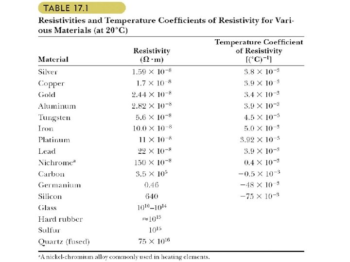
Resistivity • The resistance of an ohmic conductor is proportional to its length, L, and inversely proportional to its cross -sectional area, A – ρ is the constant of proportionality and is called the resistivity of the material – A wire of length l has a resistance R. It is pulled to length 2 l holding the volume fixed. The resistance changes by (a) Increases by a factor of 2 (b) increases by 4 (c) decreases by 2 (d) decreases by 4 (e) does not change