Peak Inverse Voltage Peak inverse voltages across diodes


 is an indication of the • effectiveness of")


- Slides: 18
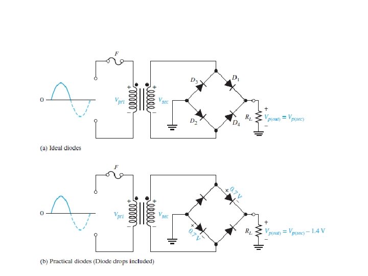
Peak Inverse Voltage Peak inverse voltages across diodes D 3 and D 4 in a bridge rectifier during the positive half-cycle of the secondary voltage.
Peak Inverse Voltage Peak inverse voltages across diodes D 3 and D 4 in a bridge rectifier during the positive half-cycle of the secondary voltage.
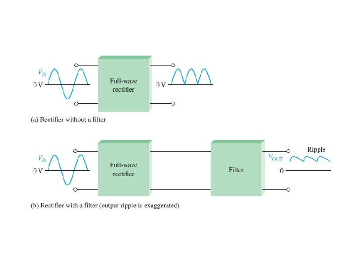
2– 6 POWER SUPPLY FILTERS AND REGULATORS A power supply filter ideally eliminates the fluctuations in • the output voltage of a half wave or full-wave rectifier and produces a constant-level dc voltage. Filtering is necessary because electronic circuits require a constant source of dc voltage and current to provide power and biasing for properation.
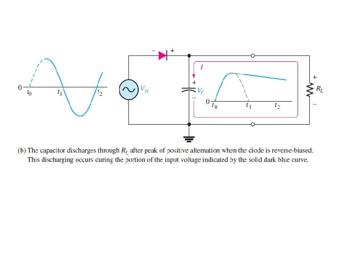
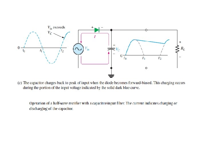
Capacitor-Input Filter
Ripple Voltage Is the variation in the capacitor voltage due to • the charging and discharging. Half-wave ripple voltage (blue line).
Comparison of ripple voltages for half-wave and full-wave rectified voltages with the same filter capacitor and load and derived from the same sinusoidal input voltage.
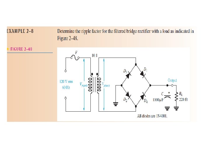
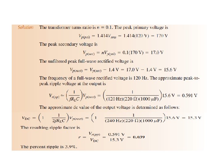
Ripple Factor The ripple factor (r) is an indication of the • effectiveness of the filter and is defined as where Vr(pp) is the peak-to-peak ripple voltage and VDC is the dc (average) value of the filter’s output voltage
For a full-wave rectifier with a capacitor-input • filter, approximations for the peak-topeak ripple voltage, Vr(pp), and the dc value of the filter output voltage, VDC, are given in the following equations. The variable Vp(rect) is the unfiltered peak rectified voltage. Notice that if RL or C increases, the ripple voltage decreases and the dc voltage increases.
Voltage Regulators Most regulators are integrated circuits and have • three terminals—an input terminal, an output terminal, and a reference (or adjust) terminal. The input to the regulator is first filtered with a capacitor to reduce the ripple to The regulator reduces the ripple to a negligible amount. In addition, most regulators have an internal voltage reference, short circuit protection, and thermal shutdown circuitry. They are available in a variety of voltages , including positive and negative outputs, and can be designed for variable outputs with a minimum of external components.
A voltage regulator with input and output capacitors.