OTU Service with one OTSi no ODUCn option


- Slides: 13

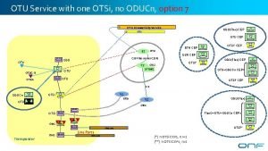
OTU Service with one OTSi, no ODUCn, option 7 OTU Connectivity Service ODU(Flex) CEP OTSi OTU CEP OTU S 2 CSEP has server CSEPs ODU OTSi#2 OTU OTSi* ODU(Flex) CEP OTU+ODUCn CEP OTU OTSi. A OTSi* CEP DSR CEP OTSi T 2 OTSi. G-O ETH CEP OTSi* CEP 1: 1 ODUCn Y 1 OTSi OTU ODU(Flex) Y 2 OTSi Flex. O+OTU+ODUCn CEP OTSi OMS Transponder OMS Line Ports OMS Link OTSi** OMS Link (*) n OTSi CEPs, n>=1 (**) n OTSi CEPs, n>1

OTU Service with two OTSi, two photonic links, option 7 OTU Connectivity Service OTSi ODU(Flex) CEP DSR OTSi T 2 OTU OTSi. G-O T 1 1: 1 ODUCn OTSi* CEP OTSi#2 OTSi#1 OTU OTSi. A OTU+ODUCn CEP CSEP has server CSEPs ODU OTU S 2 ODUFlex 1: 1 Y 1 OTSi OTU OTSi Node Edge Point Connection End Point (TTP only) Y 2 OTSi Connection End Point (CTP only) Connection End Point (TTP + CTP) Media Channel CEP {lower. Freq, upper. Freq} OTSi Connection Connectivity Service OMS Transponder OMS Line Ports OMS Link (*) n OTSi CEPs, n>=1 Service Interface Point Connectivity Service End Point

DSR/200 GE Service with two OTSi, two photonic links, option 7 200 GE Connectivity Service 200 GE DSR Connectivity Service OTSi A 1 OTSi 200 Gig. E ETH CEP 200 Gig. E DSR CEP A S 2 DSR OTSi T 2 DSR OTSi. G-O T 1 OTSi#2 OTSi#1 DSR OTSi. A OTSi* CSEP has server CSEPs DSR/FEC 1: 1 Node Edge Point Connection End Point (TTP only) ODUCn OTU DSR OTSi DSR Connection End Point Y 1 OTSi (CTP only) Y 2 OTSi Connection End Point (TTP + CTP) Media Channel CEP {lower. Freq, upper. Freq} Connection OTSi Connectivity Service Link OMS Transponder OMS Line Ports OMS Link (*) n OTSi CEPs, n>=1 Service Interface Point Connectivity Service End Point

3 R @ ODUCn, distinct Nodes , option 7 DSR Connection OTU Connectivity Service OTSi ODUCn CTP OTSi For further analysis OTUCn TCM ODUCn ODU CSEP has server CSEPs OTU ODU Link OTU S 2 (ODUCn) OTSi T 2 OTSi. G-O ODU T 1 OTSi OTU+ODUCn CEP OTSi* CEP OTSi#2 OTSi#1 OTU Node Edge Point Connection End Point 1: 2 OTSi (TTP only) Y 1 OTSi Connection End Point (CTP only) Connection End Point (TTP + CTP) Media Channel CEP {lower. Freq, upper. Freq} OTSi Connection Connectivity Service OMS Transponder OMS Link (*) n OTSi CEPs, n>=1 Service Interface Point Connectivity Service End Point

3 R @ ODUCn, Single Node , option 7 DSR Connection OTU Connectivity Service OTSi OTUCn TCM OTU S 2’ OTSi OTU T 2’ OTSi#2’ (ODUCn) CSEP has server CSEPs OTSi OTUCn TCM OTSi#1’ 1: 2 T 1 OTSi#2 OTSi#1 OTU OTSi T 2 OTSi. G-O T 1’ CSEP has server CSEPs OTU 1: 2 OTSi Y 1’ OTSi OMS Link OTSi OMS OMS Transponder OTU OTSi OMS Link

3 R @ ODU, distinct Nodes, no ODUCn, option 7 ODU 4 Connection OTU Connectivity Service OTSi ODU 4 OTSi ODU(Flex) CEP OTU CEP ODU Link ODU OTU S 1 ODU OTSi* CEP CSEP has server CSEPs OTU OTSi T 1 OTSi#1 OTSi. G-O OTU Node Edge Point Connection End Point ODUCn 1: 1 OTU (TTP only) Connection End Point (CTP only) OTSi Y 1 OTSi Connection End Point (TTP + CTP) Media Channel CEP {lower. Freq, upper. Freq} Connection OTSi Connectivity Service Link OMS Transponder OMS Link (*) n OTSi CEPs, n>=1 Service Interface Point Connectivity Service End Point

3 R @ ODUCn, Single Node, option 8 (ODUCn de-encapsulated from OTU, hence no ODUCn provisioning at OTU ODU 4 Connection CS) OTU Connectivity Service OTSi OTU OTSi ODUCn ODU S 2’ OTSi S 2 CSEP has server CSEPs OTSi OTU T 2’ OTSi#2’ OTU OTU OTSi. G-O T 1’ OTSi#1’ 1: 2 OTSi Y 1 1: 2 OTSi OMS Link OTSi#2 OTSi#1 OTSi Y 1’ OTSi T 1 OTU OTSi T 2 OTSi OMS OMS ODUCn CEP OTU CEP OTSi* CEP OMS Link Transponder (*) n OTSi CEPs, n>=1

OTU Service with two OTSi, two photonic links, option 8, ODUFlex client OTU Connectivity Service ODUFlex OTSi ODUCn and ODUFlex could be encapsulated in same CEP ODUCn ODU OTU S 2 ODUCn CSEP has server CSEPs ODU(Flex) CEP OTSi ODUCn CEP T 2 OTU OTSi. G-O T 1 OTSi#2 OTU CEP OTSi#1 OTU OTSi. A OTSi 1: 1 OTSi* CEP 1: 1 Y 1 OTSi OTU OTSi Y 2 OTSi OMS Transponder OMS Line Ports OMS Link (*) n OTSi CEPs, n>=1

OTU Service with two OTSi, two photonic links, option 8, ODU 4 client ODU 4 OTU Connectivity Service ODU 4 OTSi ODUCn OTU S 2 ODU OTU CSEP has server CSEPs ODU(Flex) CEP OTSi ODUCn CEP T 2 OTU OTSi. G-O T 1 1: 1 OTSi OMS Line Ports OMS Link OTU CEP OTSi* CEP 1: 1 Y 2 OTSi OMS OTSi#2 Y 1 OTSi OTU Transponder OTSi#1 OTU OTSi. A ODUCn and ODUk cannot be encapsulated in same CEP

3 R @ ODUCn, Single Node , option 7, e 2 e OTU Service DSR Connection OTU Connectivity Service CSEP Has Stitched CSEP OTSi DSR OTSi CSEP ODUFlex OTU S 1 ODU Has F CSEP has server CSEPs (ODUCn) OTU OTSi. G-O OTSi. A T 1 OTSi#2 er CSE P S 3 CSEP has server CSEPs OTU T 3 OTSi#2 1: 1 OTSi T 3’ OTSi OTU OTSi T 4’ OTU OTSi. G-O T 4 OTSi#b OTSi#a OTU Y 1 OTSi OTU OTSi. G-O OTSi#1 OTSi OTU S 4 (ODUCn) CSEP has server CSEPs OTSi#1 OTU ing Pe OTU OTSi T 2 orwar d Y 2 1: 2 OTSi 1: 2 OTSi Y 4 Y 3 OTSi OTSi OMS Link OMS Transponder Line Ports OMS Link WDM OMS Link OMS OMS Transponder OMS Link WDM

Broken scenario 1 To allow the implementation of 3 R forwarding, some client layer(s) parameters are necessary when provisioning Photonic Service, e. g. OTSi central frequency, Modulation Technique, ODU TTI etc. 11

Broken scenario 1 There are three Trails, but from OAM viewpoint, it is a single Connection with a complex route. Same central frequency. 12

Broken scenario 2 There are four Trails, but from OAM viewpoint, it is a single Connection with a complex route. Different central frequencies. 13
