Long Term Evolution Technology training Session 2 1

- Slides: 38
Long Term Evolution Technology training (Session 2) 1
Outline • Spectrum allocation for LTE • LTE DL Physical Layer – Management in frequency domain – Management in time domain – Management in code domain 2
Part 1 SPECTRUM ALLOCATION FOR LTE 3
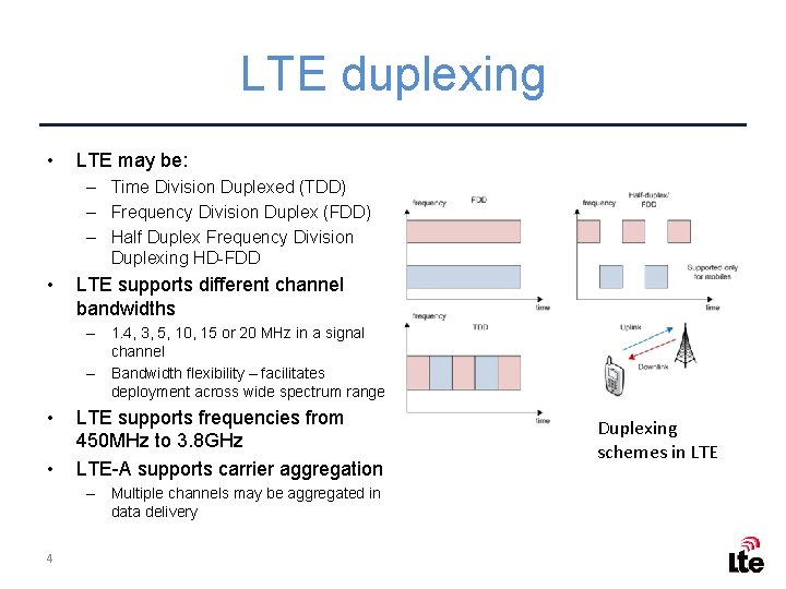
LTE duplexing • LTE may be: – Time Division Duplexed (TDD) – Frequency Division Duplex (FDD) – Half Duplex Frequency Division Duplexing HD-FDD • LTE supports different channel bandwidths – 1. 4, 3, 5, 10, 15 or 20 MHz in a signal channel – Bandwidth flexibility – facilitates deployment across wide spectrum range • • LTE supports frequencies from 450 MHz to 3. 8 GHz LTE-A supports carrier aggregation – Multiple channels may be aggregated in data delivery 4 Duplexing schemes in LTE
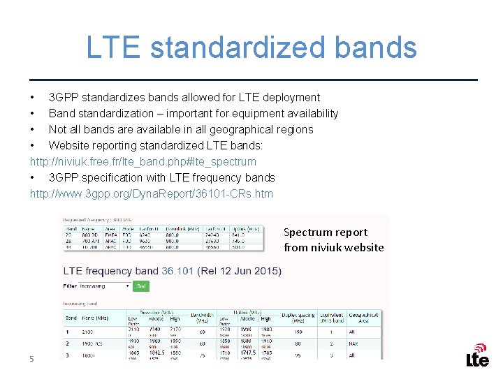
LTE standardized bands • 3 GPP standardizes bands allowed for LTE deployment • Band standardization – important for equipment availability • Not all bands are available in all geographical regions • Website reporting standardized LTE bands: http: //niviuk. free. fr/lte_band. php#lte_spectrum • 3 GPP specification with LTE frequency bands http: //www. 3 gpp. org/Dyna. Report/36101 -CRs. htm Spectrum report from niviuk website 5
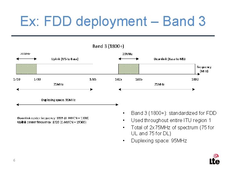
Ex: FDD deployment – Band 3 • • 6 Band 3 (1800+): standardized for FDD Used throughout entire ITU region 1 Total of 2 x 75 MHz of spectrum (75 for UL and 75 for DL) Duplexing space: 95 MHz
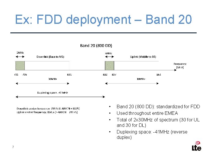
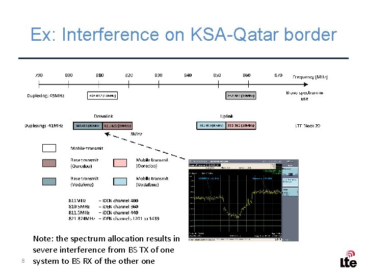
Ex: FDD deployment – Band 20 • • 7 Band 20 (800 DD): standardized for FDD Used throughout entire EMEA Total of 2 x 30 MHz of spectrum (30 for UL and 30 for DL) Duplexing space: -41 MHz (reverse duplex)
Ex: Interference on KSA-Qatar border 8 Note: the spectrum allocation results in severe interference from BS TX of one system to BS RX of the other one
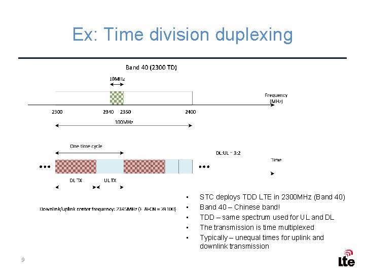
Ex: Time division duplexing • • • 9 STC deploys TDD LTE in 2300 MHz (Band 40) Band 40 – Chinese band! TDD – same spectrum used for UL and DL The transmission is time multiplexed Typically – unequal times for uplink and downlink transmission
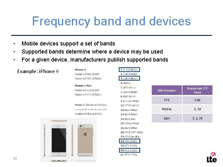
Frequency band devices • • • Mobile devices support a set of bands Supported bands determine where a device may be used For a given device, manufacturers publish supported bands Example: i. Phone 6 10 KSA Provider Supported LTE band STC 3, 40 Mobily 3, 38 Zain 3, 1, 38
Review questions • • • 11 Which LTE bands are currently used in KSA? Which LTE bands are standardized for use in Middle East Consider i. Phone 6 Model: A 1532 (GSM). Would this model work in KSA? How about Europe? Find a model of Samsung phone that could work in 800 DD band. Explain the difference between FDD and TDD. Why is there difference between downlink and uplink time allocation in LTE TDD?
Part 2 LTE DOWNLINK PHYSICAL LAYER FREQUENCY DOMAIN 12
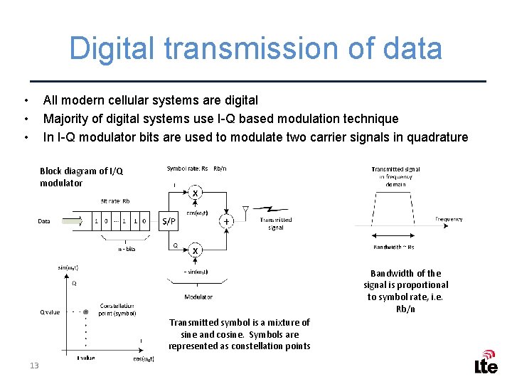
Digital transmission of data • • • All modern cellular systems are digital Majority of digital systems use I-Q based modulation technique In I-Q modulator bits are used to modulate two carrier signals in quadrature Block diagram of I/Q modulator Bandwidth of the signal is proportional to symbol rate, i. e. Rb/n Transmitted symbol is a mixture of sine and cosine. Symbols are represented as constellation points 13
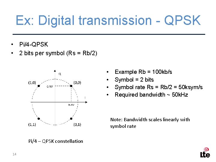
Ex: Digital transmission - QPSK • Pi/4 -QPSK • 2 bits per symbol (Rs = Rb/2) • • Example Rb = 100 kb/s Symbol = 2 bits Symbol rate Rs = Rb/2 = 50 ksym/s Required bandwidth ~ 50 k. Hz Note: Bandwidth scales linearly with symbol rate Pi/4 – QPSK constellation 14
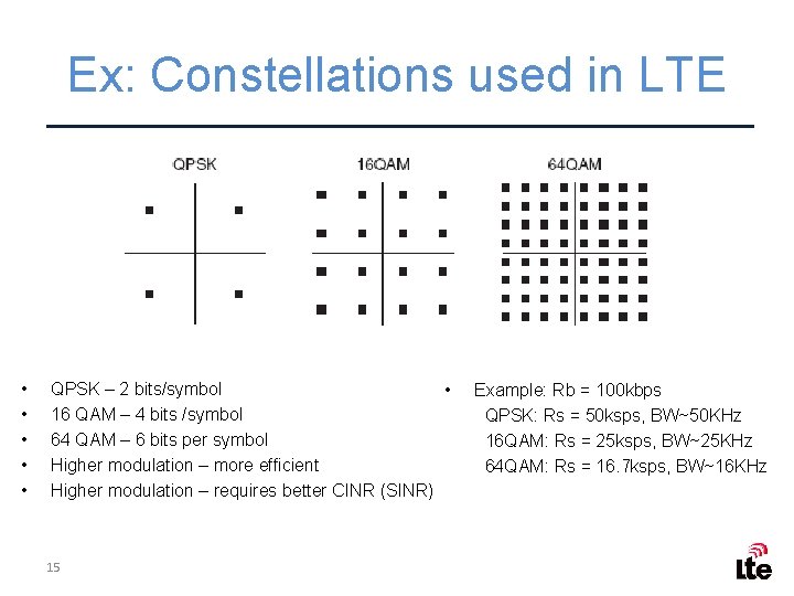
Ex: Constellations used in LTE • • • QPSK – 2 bits/symbol • 16 QAM – 4 bits /symbol 64 QAM – 6 bits per symbol Higher modulation – more efficient Higher modulation – requires better CINR (SINR) 15 Example: Rb = 100 kbps QPSK: Rs = 50 ksps, BW~50 KHz 16 QAM: Rs = 25 ksps, BW~25 KHz 64 QAM: Rs = 16. 7 ksps, BW~16 KHz
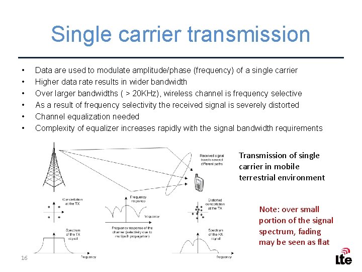
Single carrier transmission • • • Data are used to modulate amplitude/phase (frequency) of a single carrier Higher data rate results in wider bandwidth Over larger bandwidths ( > 20 KHz), wireless channel is frequency selective As a result of frequency selectivity the received signal is severely distorted Channel equalization needed Complexity of equalizer increases rapidly with the signal bandwidth requirements Transmission of single carrier in mobile terrestrial environment Note: over small portion of the signal spectrum, fading may be seen as flat 16
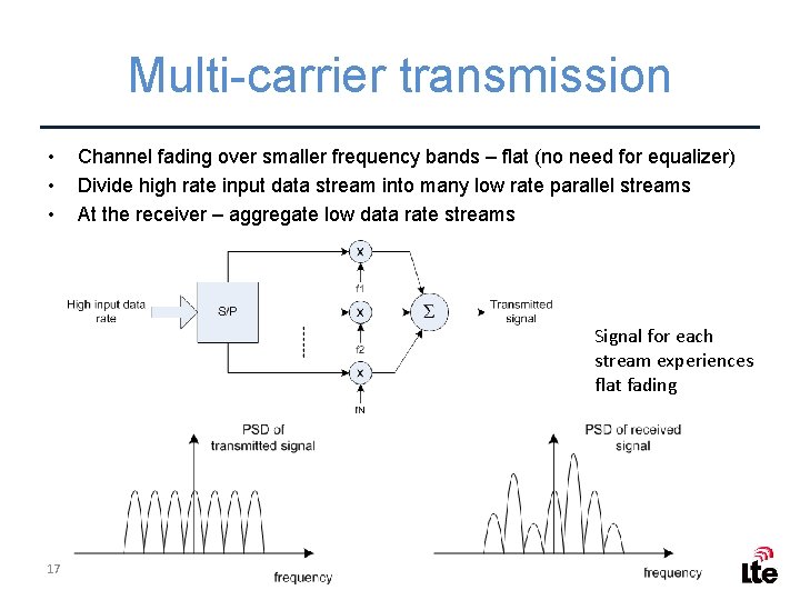
Multi-carrier transmission • • • Channel fading over smaller frequency bands – flat (no need for equalizer) Divide high rate input data stream into many low rate parallel streams At the receiver – aggregate low data rate streams Signal for each stream experiences flat fading 17
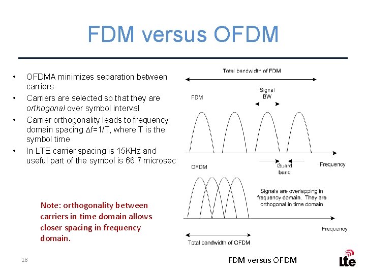
FDM versus OFDM • • OFDMA minimizes separation between carriers Carriers are selected so that they are orthogonal over symbol interval Carrier orthogonality leads to frequency domain spacing Df=1/T, where T is the symbol time In LTE carrier spacing is 15 KHz and useful part of the symbol is 66. 7 microsec Note: orthogonality between carriers in time domain allows closer spacing in frequency domain. 18 FDM versus OFDM
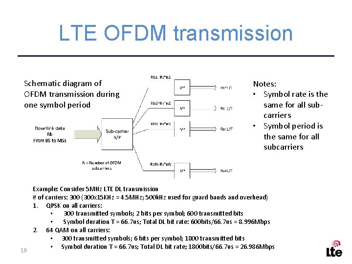
LTE OFDM transmission Schematic diagram of OFDM transmission during one symbol period 19 Notes: • Symbol rate is the same for all subcarriers • Symbol period is the same for all subcarriers Example: Consider 5 MHz LTE DL transmission # of carriers: 300 (300 x 15 KHz = 4. 5 MHz; 500 k. Hz used for guard bands and overhead) 1. QPSK on all carriers: • 300 transmitted symbols; 2 bits per symbol; 600 transmitted bits • Symbol duration T = 66. 7 us; Total DL bit rate: 600 bits/66. 7 us = 8. 996 Mbps 2. 64 QAM on all carriers: • 300 transmitted symbols; 6 bits per symbol; 1800 transmitted bits • Symbol duration T = 66. 7 us; Total DL bit rate; 1800 bits/66. 7 us = 26. 986 Mbps
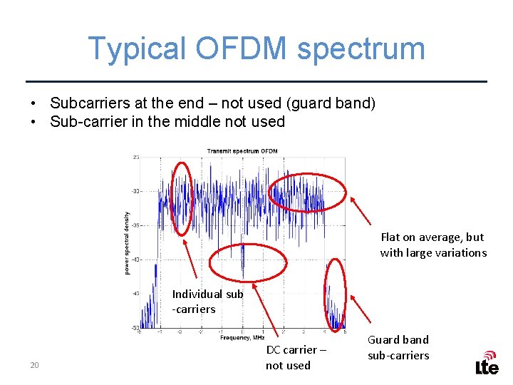
Typical OFDM spectrum • Subcarriers at the end – not used (guard band) • Sub-carrier in the middle not used Flat on average, but with large variations Individual sub -carriers 20 DC carrier – not used Guard band sub-carriers
Review questions • • 21 What modulation scheme is used on LTE downlink? What is the sub-carrier separation on LTE downlink? What is the symbol duration on LTE downlink? What modulation schemes are available for LT downlink? How many bits per symbol are used in 16 QAM? If the modulation scheme is QPSK and bit rate is 120 kbps, what is the symbol rate? Consider an LTE deployment in 15 MHz. The number of data sub -carriers is 900. Determine total number of bits that may be transmitted over one symbol interval, if 16 QAM is used on all subcarriers.
Part 3 LTE DOWNLINK PHYSICAL LAYER TIME DOMAIN 22
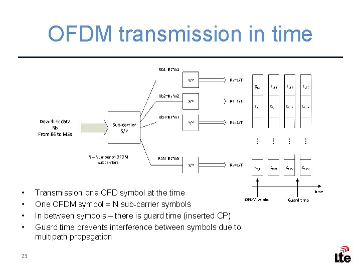
OFDM transmission in time • • 23 Transmission one OFD symbol at the time One OFDM symbol = N sub-carrier symbols In between symbols – there is guard time (inserted CP) Guard time prevents interference between symbols due to multipath propagation
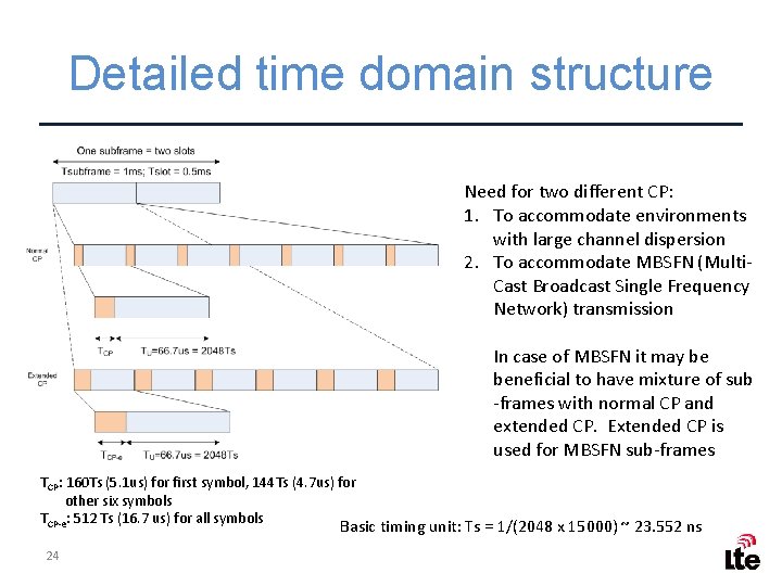
Detailed time domain structure Need for two different CP: 1. To accommodate environments with large channel dispersion 2. To accommodate MBSFN (Multi. Cast Broadcast Single Frequency Network) transmission In case of MBSFN it may be beneficial to have mixture of sub -frames with normal CP and extended CP. Extended CP is used for MBSFN sub-frames TCP: 160 Ts (5. 1 us) for first symbol, 144 Ts (4. 7 us) for other six symbols TCP-e: 512 Ts (16. 7 us) for all symbols Basic timing unit: Ts = 1/(2048 x 15000) ~ 23. 552 ns 24
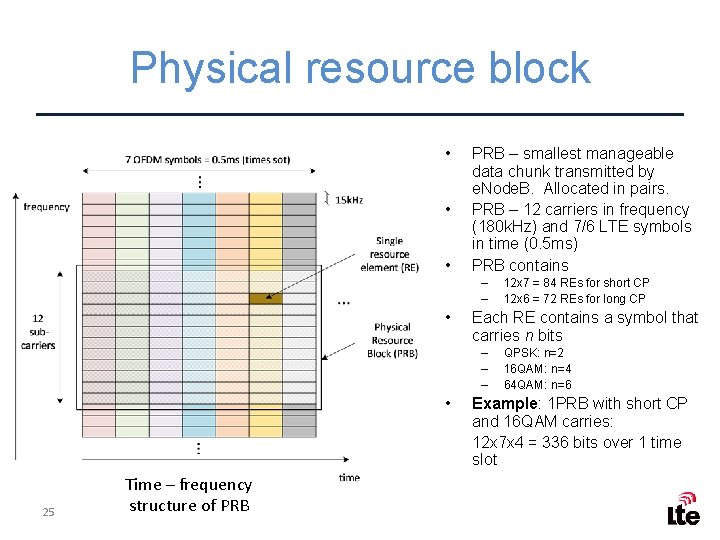
Physical resource block • • • PRB – smallest manageable data chunk transmitted by e. Node. B. Allocated in pairs. PRB – 12 carriers in frequency (180 k. Hz) and 7/6 LTE symbols in time (0. 5 ms) PRB contains – – • Each RE contains a symbol that carries n bits – – – • 25 Time – frequency structure of PRB 12 x 7 = 84 REs for short CP 12 x 6 = 72 REs for long CP QPSK: n=2 16 QAM: n=4 64 QAM: n=6 Example: 1 PRB with short CP and 16 QAM carries: 12 x 7 x 4 = 336 bits over 1 time slot
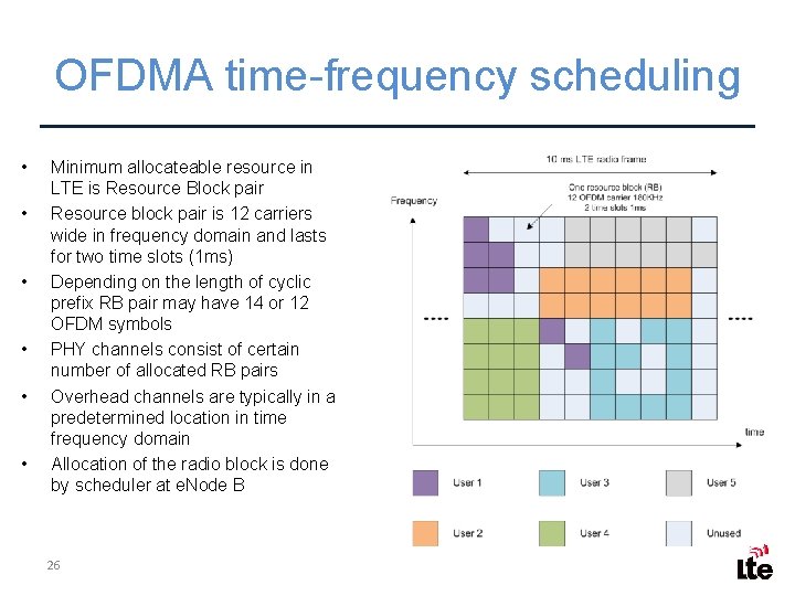
OFDMA time-frequency scheduling • • • Minimum allocateable resource in LTE is Resource Block pair Resource block pair is 12 carriers wide in frequency domain and lasts for two time slots (1 ms) Depending on the length of cyclic prefix RB pair may have 14 or 12 OFDM symbols PHY channels consist of certain number of allocated RB pairs Overhead channels are typically in a predetermined location in time frequency domain Allocation of the radio block is done by scheduler at e. Node B 26
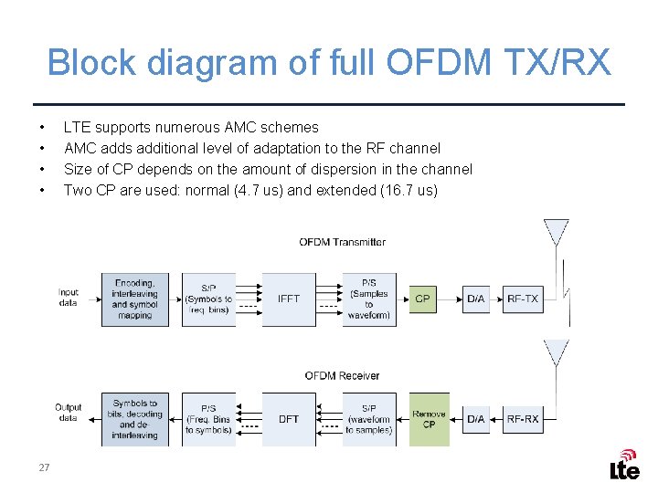
Block diagram of full OFDM TX/RX • • 27 LTE supports numerous AMC schemes AMC adds additional level of adaptation to the RF channel Size of CP depends on the amount of dispersion in the channel Two CP are used: normal (4. 7 us) and extended (16. 7 us)
Part 4 LTE DOWNLINK PHYSICAL LAYER MODULATION SCHEME 28
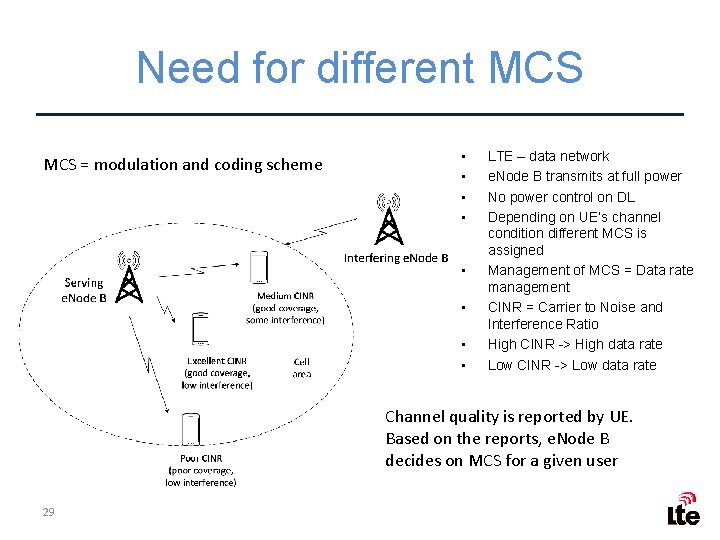
Need for different MCS = modulation and coding scheme • • LTE – data network e. Node B transmits at full power No power control on DL Depending on UE’s channel condition different MCS is assigned Management of MCS = Data rate management CINR = Carrier to Noise and Interference Ratio High CINR -> High data rate Low CINR -> Low data rate Channel quality is reported by UE. Based on the reports, e. Node B decides on MCS for a given user 29
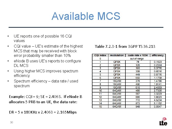
Available MCS • UE reports one of possible 16 CQI values CQI value – UE’s estimate of the highest MCS that may be received with block error probability smaller than 10% e. Node B uses UE’s reports to configure DL MCS Using higher MCS improves spectrum efficiency Spectrum efficiency – data rate / used spectrum • • Example: CQI = 9; SE = 2. 4063. If e. Node B allocates 5 PRB to an UE, the data rate: DR = 5 x 180 KHz x 2. 4063 = 2. 165 Mbps 30 Table 7. 2. 3 -1 from 3 GPP TS 36. 213
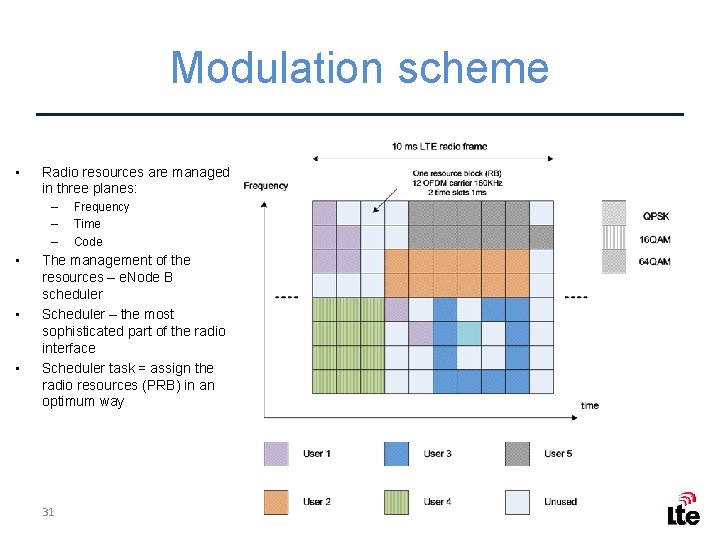
Modulation scheme • Radio resources are managed in three planes: – – – • • • Frequency Time Code The management of the resources – e. Node B scheduler Scheduler – the most sophisticated part of the radio interface Scheduler task = assign the radio resources (PRB) in an optimum way 31
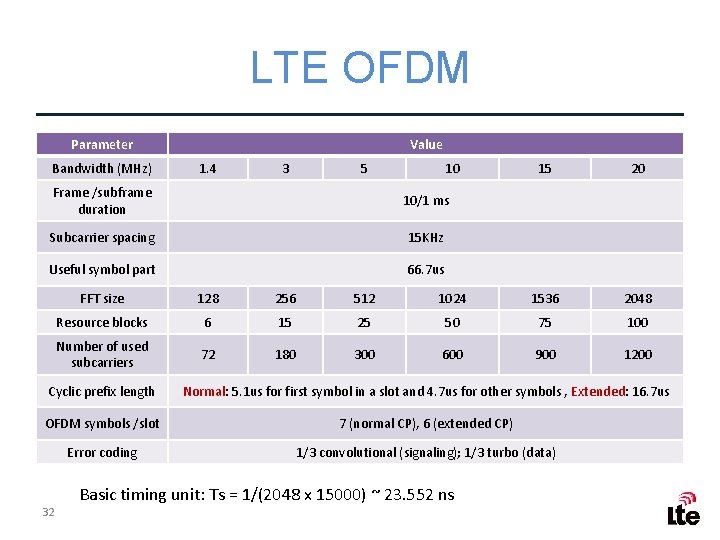
LTE OFDM Parameter Bandwidth (MHz) Value 1. 4 3 5 10 Frame /subframe duration 10/1 ms Subcarrier spacing 15 KHz Useful symbol part 66. 7 us 15 20 FFT size 128 256 512 1024 1536 2048 Resource blocks 6 15 25 50 75 100 Number of used subcarriers 72 180 300 600 900 1200 Cyclic prefix length Normal: 5. 1 us for first symbol in a slot and 4. 7 us for other symbols , Extended: 16. 7 us OFDM symbols /slot 7 (normal CP), 6 (extended CP) Error coding 1/3 convolutional (signaling); 1/3 turbo (data) 32 Basic timing unit: Ts = 1/(2048 x 15000) ~ 23. 552 ns
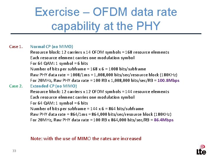
Exercise – OFDM data rate capability at the PHY Case 1. Case 2. Normal CP (no MIMO) Resource block: 12 carriers x 14 OFDM symbols = 168 resource elements Each resource element carries one modulation symbol For 64 QAM: 1 symbol = 6 bits Number of bits per subframe = 168 x 6 = 1008 bits/subframe Raw PHY data rate = 1008/1 ms = 1, 008, 000 bits/sec/resource block (180 KHz) For 20 MHz, Raw PHY data rate = 100 RB x 1, 008, 000 bits/sec/RB = 100. 8 Mbps Extended CP (no MIMO) Resource block: 12 carriers x 12 OFDM symbols = 144 resource elements Each resource element carries one modulation symbol For 64 QAM: 1 symbol = 6 bits Number of bits per subframe = 144 x 6 = 864 bits/subframe Raw PHY data rate = 864/1 ms = 864, 000 bits/sec/resource block (180 KHz) For 20 MHz, Raw PHY data rate = 100 RB x 864, 000 bits/sec/RB = 86. 4 Mbps Note: with the use of MIMO the rates are increased 33
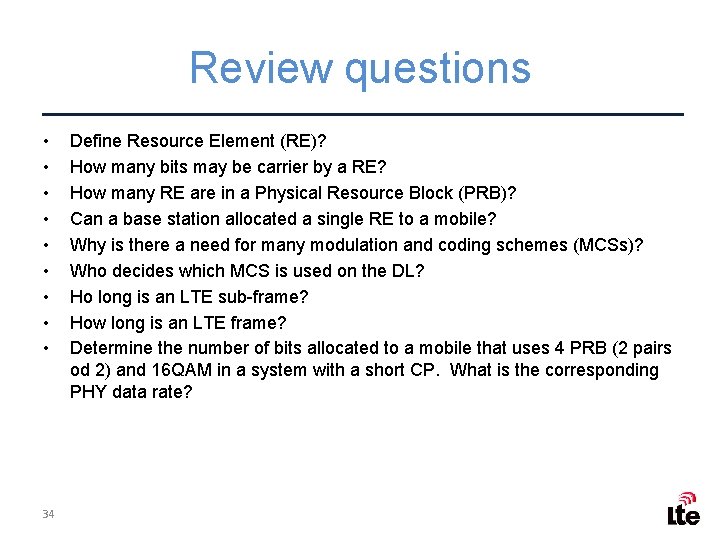
Review questions • • • 34 Define Resource Element (RE)? How many bits may be carrier by a RE? How many RE are in a Physical Resource Block (PRB)? Can a base station allocated a single RE to a mobile? Why is there a need for many modulation and coding schemes (MCSs)? Who decides which MCS is used on the DL? Ho long is an LTE sub-frame? How long is an LTE frame? Determine the number of bits allocated to a mobile that uses 4 PRB (2 pairs od 2) and 16 QAM in a system with a short CP. What is the corresponding PHY data rate?
Part 6 EXTRA 35
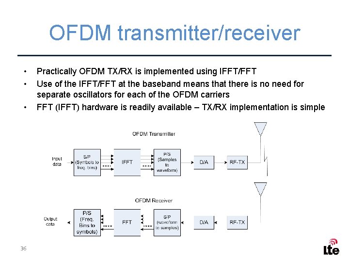
OFDM transmitter/receiver • • • 36 Practically OFDM TX/RX is implemented using IFFT/FFT Use of the IFFT/FFT at the baseband means that there is no need for separate oscillators for each of the OFDM carriers FFT (IFFT) hardware is readily available – TX/RX implementation is simple
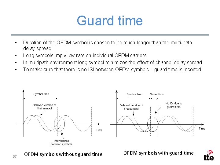
Guard time • • 37 Duration of the OFDM symbol is chosen to be much longer than the multi-path delay spread Long symbols imply low rate on individual OFDM carriers In multipath environment long symbol minimizes the effect of channel delay spread To make sure that there is no ISI between OFDM symbols – guard time is inserted OFDM symbols without guard time OFDM symbols with guard time
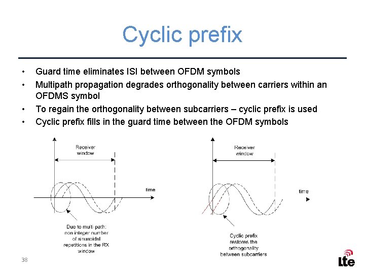
Cyclic prefix • • 38 Guard time eliminates ISI between OFDM symbols Multipath propagation degrades orthogonality between carriers within an OFDMS symbol To regain the orthogonality between subcarriers – cyclic prefix is used Cyclic prefix fills in the guard time between the OFDM symbols