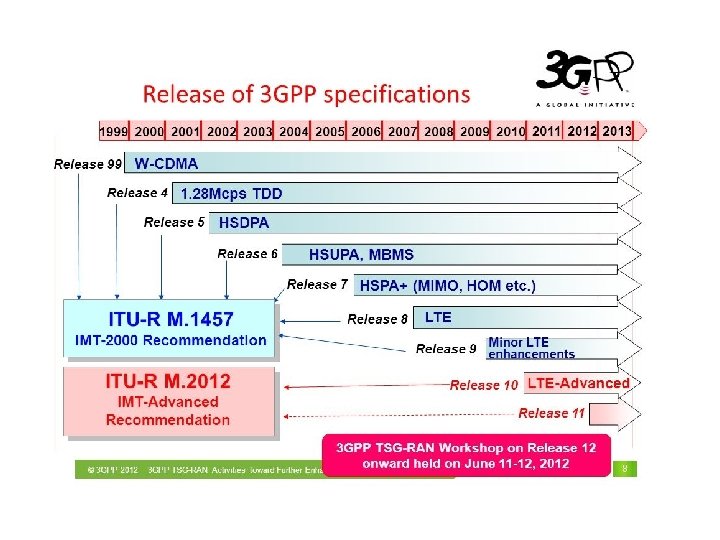
Long Term Evolution LTE Long Term Evolution Advanced
 Long Term Evolution – Advanced (LTE-A) Cont.")


 for downlink")
 • Improved spectral efficiency • Reduce ISI effect by multipath • Against")


 = 2 phase shifts, 1 amplitude level,")
")
 • Use of multiple component carriers(CC)")
- Slides: 29
Long Term Evolution (LTE) Long Term Evolution – Advanced (LTE-A) Cont.
LTE frequency bands
UMTS Architecture
LTE Architecture
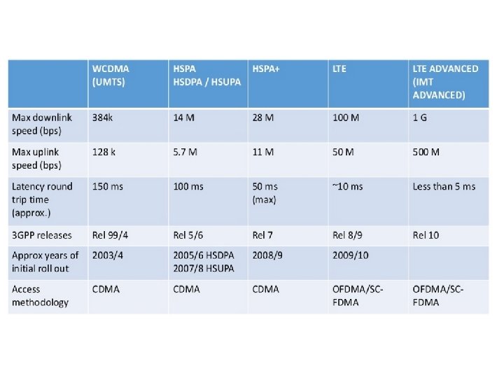
LTE vs UMTS • Functional changes compared to the current UMTS architecture
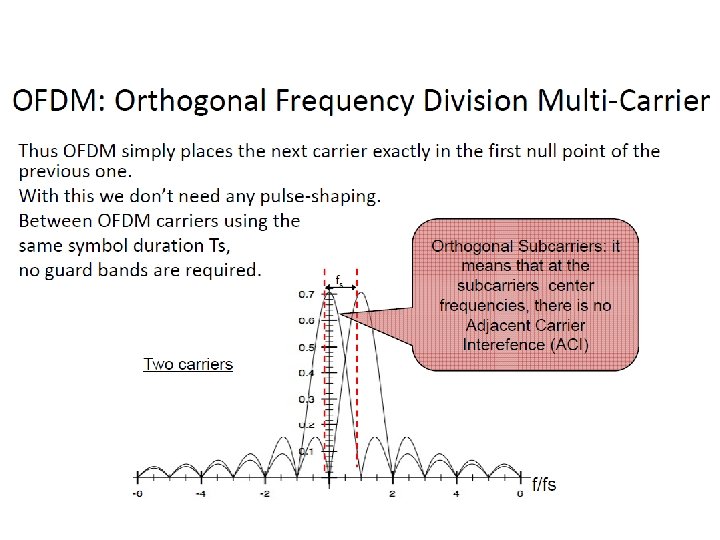
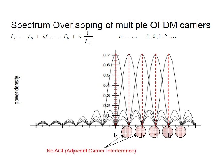
LTE Transmission Techniques • LTE employs Orthogonal Frequency Division Multiple Access (OFDMA) for downlink data transmission and Single Carrier FDMA (SCFDMA) for uplink transmission
LTE-Downlink (OFDM) • Improved spectral efficiency • Reduce ISI effect by multipath • Against frequency selective fading
FDM vs. OFDM 14
OFDM pros and cons Pros • Spectral efficiency • Robust against narrow-band co-channel interference • Higher throughput in the same frequency band (more subcarriers) Cons • It is more sensitive to carrier frequency offsets • More energy requirements due to high peak-to-average power ratio (PAPR)
SC/OFDMA
OFDMA allocation
OFDMA allocation
OFDMA/TDD structure
OFDMA/TDD structure
OFDMA/TDD structure
Generic Frame Structure
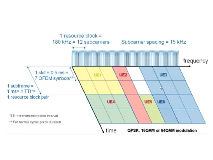
Resource Grid One downlink slot, Tslot 6 or 7 OFDM symbols Resource block : Transmission BW Resource element 12 subcarriers : l=0 l=6 • 6 or 7 OFDM symbols in 1 slot • Subcarrier spacing = 15 k. Hz • Block of 12 SCs in 1 slot = 1 RB – 0. 5 ms x 180 k. Hz – Smallest unit of allocation
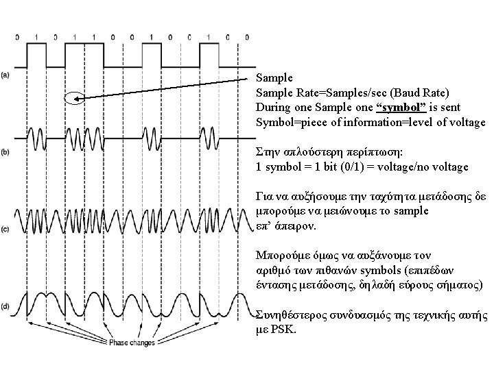
• BPSK (Binary Phase Shift Keying) = 2 phase shifts, 1 amplitude level, 1 bit/symbol • QPSK (Quadrature Phase Shift Keying) = 4 phase shifts, 1 amplitude level, 2 bits/symbol • QAM-16 = 4 phase shifts, 4 amplitude levels, 4 bits/symbol • QAM-64 = 4 phase shifts, 16 amplitude levels, 6 bits/symbol QPSK QAM-16 QAM-64
Long Term Evolution Advanced (LTEA)
LTE-A main features Support of Wider Bandwidth(Carrier Aggregation) • Use of multiple component carriers(CC) to extend bandwidth up to 100 MHz • Common physical layer parameters between component carrier and LTE Rel-8 carrier è Improvement of peak data rate, backward compatibility with LTE Rel-8 Advanced MIMO techniques • • • è Extension to up to 8 -layer transmission in downlink Introduction of single-user MIMO up to 4 -layer transmission in uplink Enhancements of multi-user MIMO Improvement of peak data rate and capacity Heterogeneous network and e. ICIC (enhanced Inter-Cell Interference Coordination) • Interference coordination for overlaid deployment of cells with different Tx power è Improvement of cell-edge throughput and coverage Relay • Supports radio backhaul and creates a separate cell and appear as Rel. 8 LTE e. NB to Rel. 8 LTE UEs è Improvement of coverage and flexibility of service area extension Coordinated Multi-Point transmission and reception (Co. MP) • Support of multi-cell transmission and reception è Improvement of cell-edge throughput and coverage 100 MHz f CC