Lit Literatuur KKennen TAToepassenAfleiden College 9 Hecht H
- Slides: 50
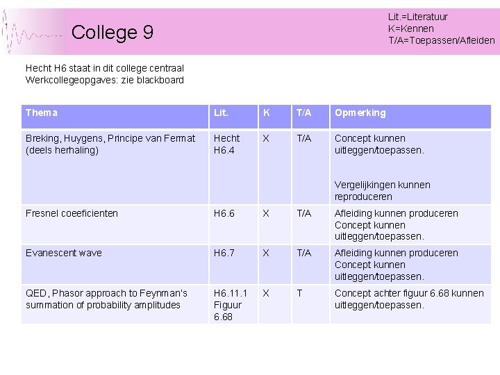
Lit. =Literatuur K=Kennen T/A=Toepassen/Afleiden College 9 Hecht H 6 staat in dit college centraal Werkcollegeopgaves: zie blackboard Thema Lit. K T/A Opmerking Breking, Huygens, Principe van Fermat (deels herhaling) Hecht H 6. 4 X T/A Concept kunnen uitleggen/toepassen. Vergelijkingen kunnen reproduceren Fresnel coeeficienten H 6. 6 X T/A Afleiding kunnen produceren Concept kunnen uitleggen/toepassen. Evanescent wave H 6. 7 X T/A Afleiding kunnen produceren Concept kunnen uitleggen/toepassen. QED, Phasor approach to Feynman’s summation of probability amplitudes H 6. 11. 1 Figuur 6. 68 X T Concept achter figuur 6. 68 kunnen uitleggen/toepassen.
Trillingen, Golven en Optica (TGO) n n TGO in dagelijks leven: geluid, licht en mechanische trillingen. TGO in de natuurkunde: belangrijke basiskennis om verschijnselen uit de Quantum Mechanica en Electromagnetisme te beschrijven en te begrijpen. Dr. Marcel Vreeswijk h 73@nikhef. nl, Nikhef Prof. Dr. Johannes F. de Boer jfdeboer@few. vu. nl, Laserlab VU Januari Feb-Maart Trillingen & Golven & Optica 2
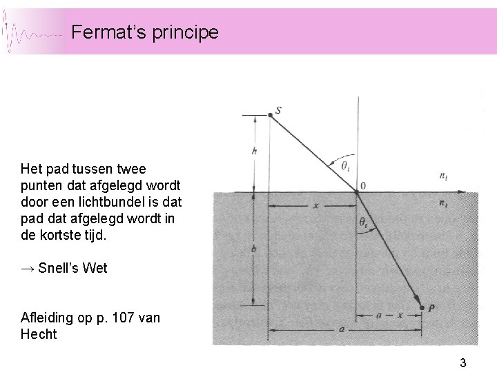
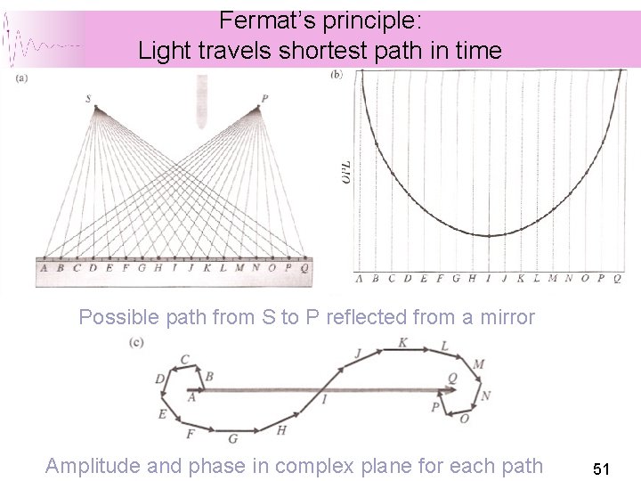
Fermat’s principe Het pad tussen twee punten dat afgelegd wordt door een lichtbundel is dat pad dat afgelegd wordt in de kortste tijd. → Snell’s Wet Afleiding op p. 107 van Hecht 3
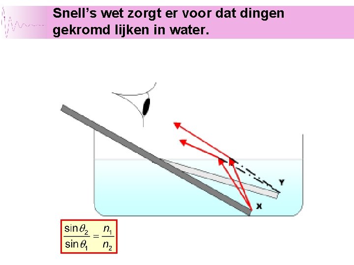
Snell’s wet zorgt er voor dat dingen gekromd lijken in water.
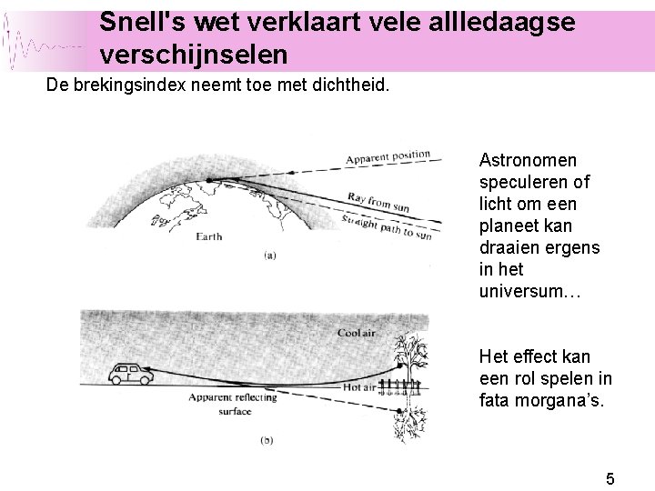
Snell's wet verklaart vele allledaagse verschijnselen De brekingsindex neemt toe met dichtheid. Astronomen speculeren of licht om een planeet kan draaien ergens in het universum… Het effect kan een rol spelen in fata morgana’s. 5
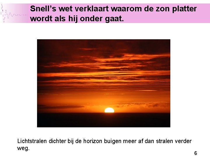
Snell’s wet verklaart waarom de zon platter wordt als hij onder gaat. Lichtstralen dichter bij de horizon buigen meer af dan stralen verder weg. 6
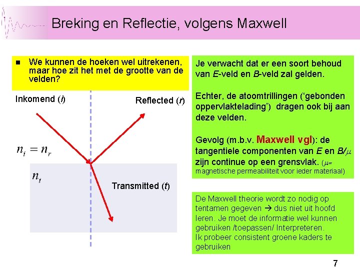
Breking en Reflectie, volgens Maxwell n We kunnen de hoeken wel uitrekenen, maar hoe zit het met de grootte van de velden? Inkomend (i) Reflected (r) Je verwacht dat er een soort behoud van E-veld en B-veld zal gelden. Echter, de atoomtrillingen (‘gebonden oppervlaktelading’) dragen ook bij aan deze velden. Gevolg (m. b. v. Maxwell vgl): de tangentiele componenten van E en B/m zijn continue op een grensvlak. (m= magnetische permeabiliteit voor ieder materiaal) Transmitted (t) De Maxwell theorie wordt zo nodig op tentamen gegeven dus niet uit hoofd leren. Je moet de informatie wel kunnen gebruiken /toepassen/ Interpreteren. Ik probeer consistent groene kaders te gebruiken 7
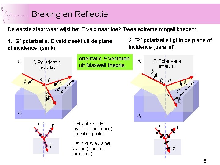
Breking en Reflectie De eerste stap: waar wijst het E veld naar toe? Twee extreme mogelijkheden: 1. “S” polarisatie. E veld steekt uit de plane of incidence. (senk) 2. “P” polarisatie ligt in de plane of incidence (parallel) orientatie E vectoren uit Maxwell theorie. S-Polarisatie invalsvlak i r t V va lak n ov er ga ga ng ng invalsvlak P-Polarisatie Het vlak van de overgang (interface) steekt uit papier. Het invalsvlak is het papier. (plane of incidence) r i t 8
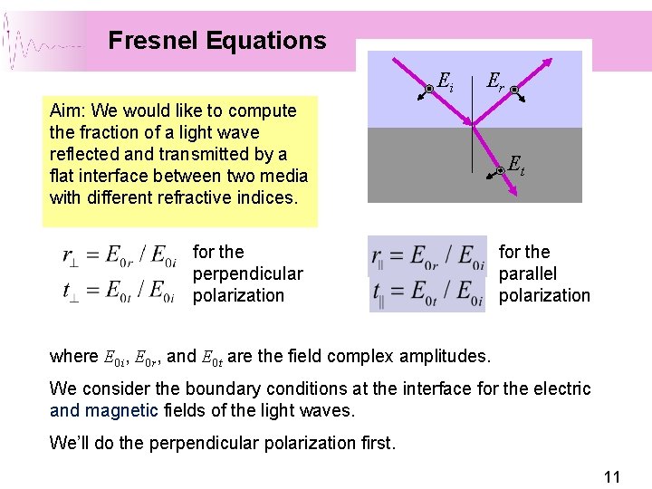
Fresnel Equations Ei Er Aim: We would like to compute the fraction of a light wave reflected and transmitted by a flat interface between two media with different refractive indices. for the perpendicular polarization Et for the parallel polarization where E 0 i, E 0 r, and E 0 t are the field complex amplitudes. We consider the boundary conditions at the interface for the electric and magnetic fields of the light waves. We’ll do the perpendicular polarization first. 11
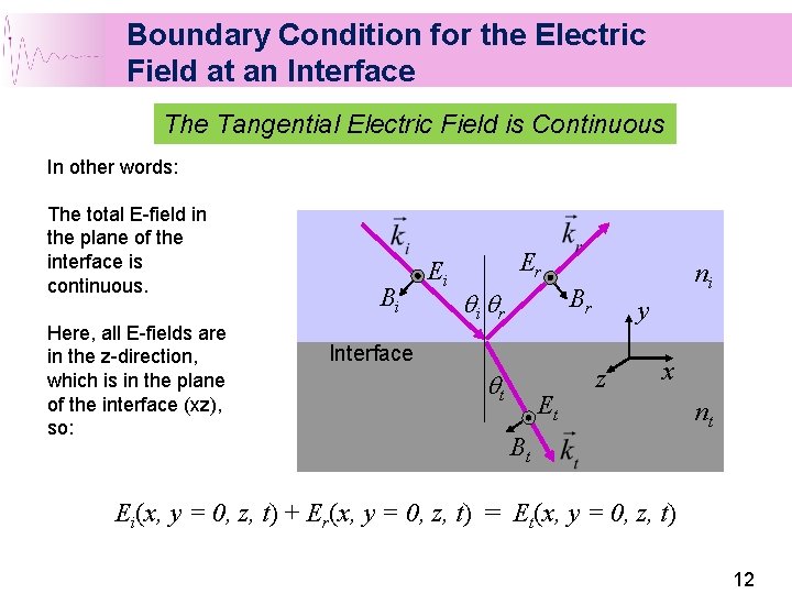
Boundary Condition for the Electric Field at an Interface The Tangential Electric Field is Continuous In other words: The total E-field in the plane of the interface is continuous. Here, all E-fields are in the z-direction, which is in the plane of the interface (xz), so: Bi Ei Er ni Br qi qr Interface qt Et y z x nt Bt Ei(x, y = 0, z, t) + Er(x, y = 0, z, t) = Et(x, y = 0, z, t) 12
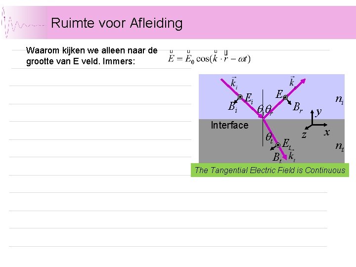
Ruimte voor Afleiding Waarom kijken we alleen naar de grootte van E veld. Immers: Bi Ei Interface qiqr qt Er Et Bt Br z ni y x nt The Tangential Electric Field is Continuous
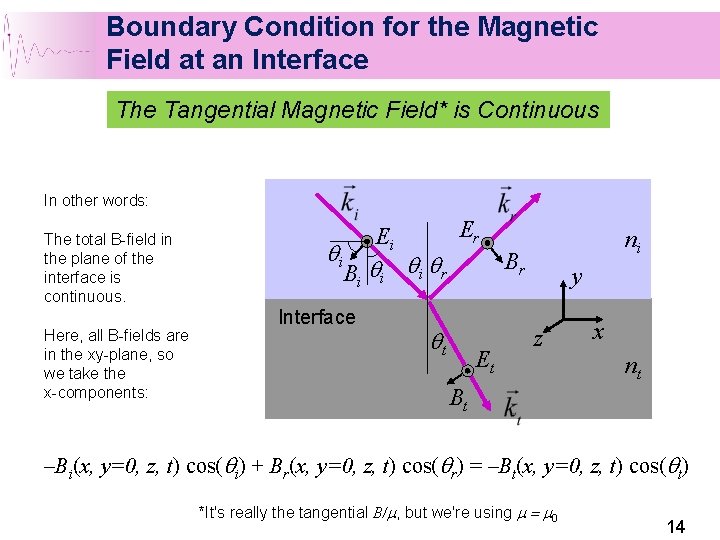
Boundary Condition for the Magnetic Field at an Interface The Tangential Magnetic Field* is Continuous In other words: The total B-field in the plane of the interface is continuous. Here, all B-fields are in the xy-plane, so we take the x-components: qi Er Ei Bi qi qi qr Interface ni Br qt Et y z x nt Bt –Bi(x, y=0, z, t) cos(qi) + Br(x, y=0, z, t) cos(qr) = –Bt(x, y=0, z, t) cos(qt) *It's really the tangential B/m, but we're using m = m 0 14
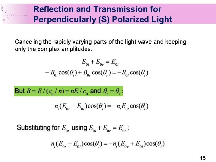
Reflection and Transmission for Perpendicularly (S) Polarized Light Canceling the rapidly varying parts of the light wave and keeping only the complex amplitudes: 15
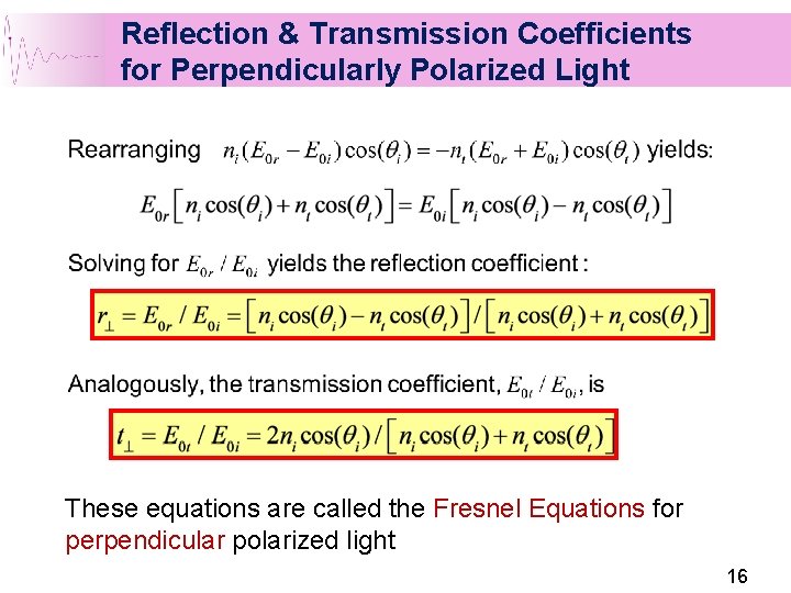
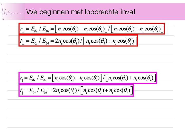
Reflection & Transmission Coefficients for Perpendicularly Polarized Light These equations are called the Fresnel Equations for perpendicular polarized light 16
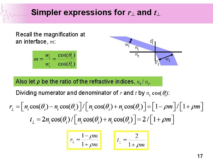
Simpler expressions for r┴ and t┴ Recall the magnification at an interface, m: wi ni nt qi θt wt Also let ρ be the ratio of the refractive indices, nt / ni. Dividing numerator and denominator of r and t by ni cos(qi): 17
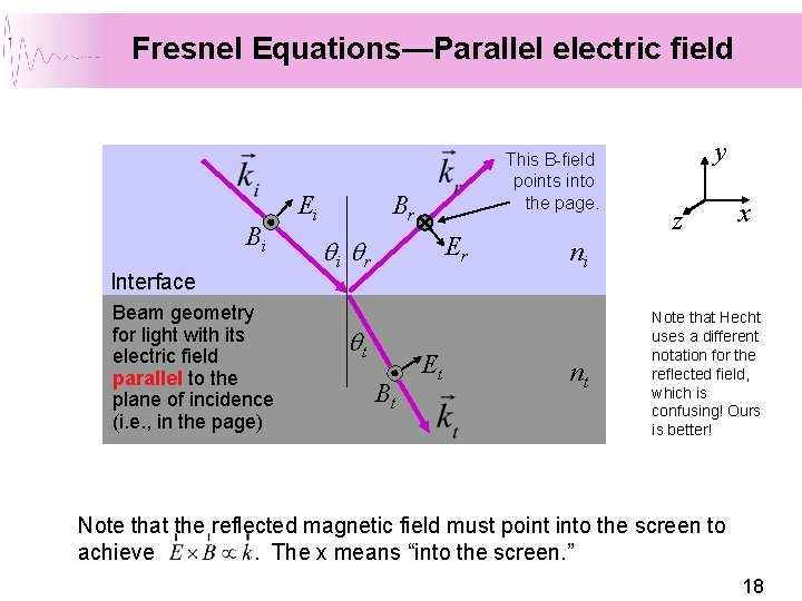
Fresnel Equations—Parallel electric field Bi Interface Beam geometry for light with its electric field parallel to the plane of incidence (i. e. , in the page) Ei This B-field points into the page. Br Er qi qr qt Bt Et y z x ni nt Note that Hecht uses a different notation for the reflected field, which is confusing! Ours is better! Note that the reflected magnetic field must point into the screen to achieve. The x means “into the screen. ” 18
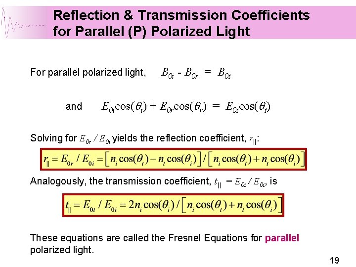
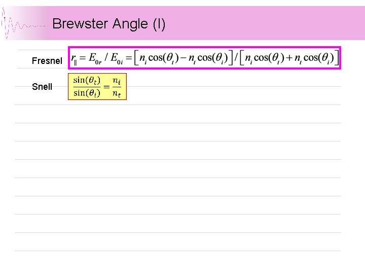
Reflection & Transmission Coefficients for Parallel (P) Polarized Light For parallel polarized light, and B 0 i - B 0 r = B 0 t E 0 icos(qi) + E 0 rcos(qr) = E 0 tcos(qt) Solving for E 0 r / E 0 i yields the reflection coefficient, r||: Analogously, the transmission coefficient, t|| = E 0 t / E 0 i, is These equations are called the Fresnel Equations for parallel polarized light. 19
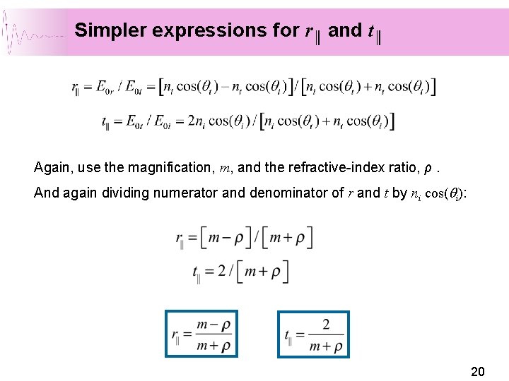
Simpler expressions for r║ and t║ Again, use the magnification, m, and the refractive-index ratio, ρ. And again dividing numerator and denominator of r and t by ni cos(qi): 20
Interpretatie van de hoeken • • • Brewster angle Critical angle Phase shifts 21
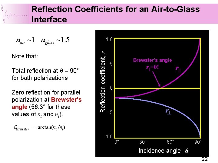
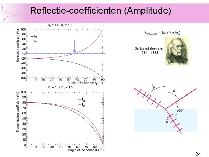
Reflection Coefficients for an Air-to-Glass Interface Note that: Total reflection at q = 90° for both polarizations Zero reflection for parallel polarization at Brewster's angle (56. 3° for these values of ni and nt). 1. 0 Reflection coefficient, r nair ~1 nglass ~1. 5 Brewster’s angle . 5 r||=0! r|| 0 r┴ -. 5 q. Brewster = arctan(nt /ni) -1. 0 0° 30° 60° 90° Incidence angle, qi 22
Brewster Angle (I) Fresnel Snell
Reflectie-coefficienten (Amplitude) 24
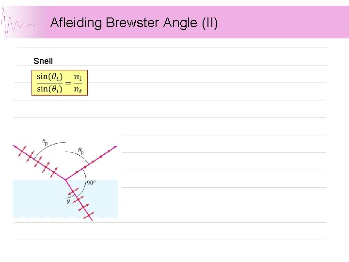
Afleiding Brewster Angle (II) Snell
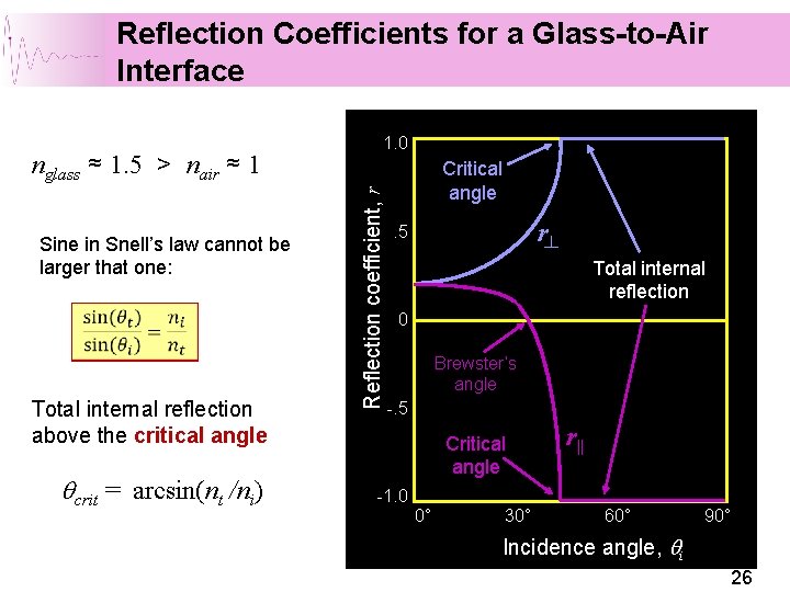
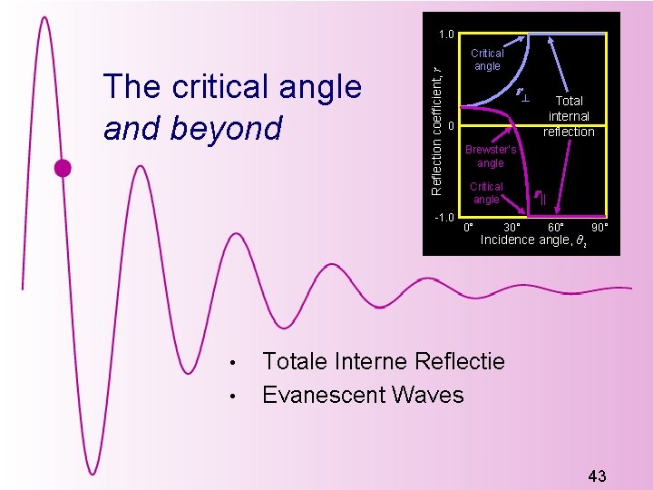
Reflection Coefficients for a Glass-to-Air Interface Sine in Snell’s law cannot be larger that one: Total internal reflection above the critical angle qcrit = arcsin(nt /ni) Reflection coefficient, r nglass ≈ 1. 5 > nair ≈ 1 1. 0 Critical angle r┴ . 5 Total internal reflection 0 Brewster’s angle -. 5 Critical angle -1. 0 0° 30° r|| 60° 90° Incidence angle, qi 26
Interpretatie Fresnel Coefficienten, vervolg Fase verschuiving reflectie 27
We beginnen met loodrechte inval
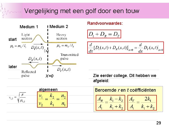
Vergelijking met een golf door een touw Medium 1 Medium 2 Randvoorwaardes: start later X=0 Zie eerder college. Dit hebben we afgeleid: algemeen Beroemde r en t coëfficiënten 29
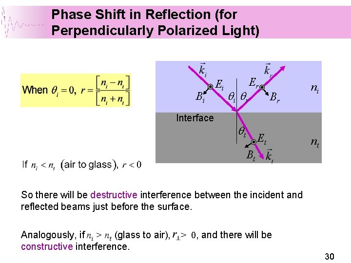
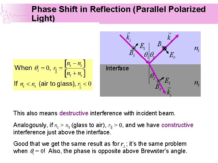
Phase Shift in Reflection (for Perpendicularly Polarized Light) Bi Interface Ei qi qr Er qt Br Et Bt ni nt So there will be destructive interference between the incident and reflected beams just before the surface. Analogously, if ni > nt (glass to air), constructive interference. > 0, and there will be 30
Phase Shift in Reflection (Parallel Polarized Light) Bi Interface Br Ei qi qr Er qt Bt Et This also means destructive interference with incident beam. Analogously, if ni > nt (glass to air), r|| > 0, and we have constructive interference just above the interface. Good that we get the same result as for ; it’s the same problem when qi = 0! Also, the phase is opposite above Brewster’s angle. ni nt
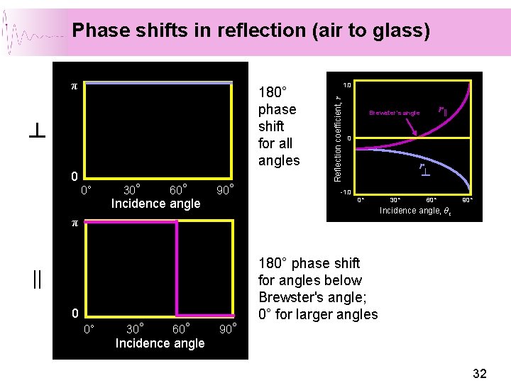
Phase shifts in reflection (air to glass) 180° phase shift for all angles ┴ 0 0° 30° 60° Incidence angle 90° 1. 0 Reflection coefficient, r π 0 r ┴ -1. 0 0° || 0 30° 60° Incidence angle 30° 60° 90° Incidence angle, θ i π 0° r|| Brewster’s angle 90° 180° phase shift for angles below Brewster's angle; 0° for larger angles 32
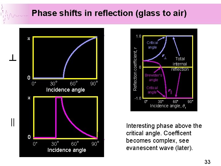
Phase shifts in reflection (glass to air) ┴ 0 0° 30° 60° Incidence angle 90° π Reflection coefficient, r 1. 0 π Critical angle r ┴ 0 -1. 0 || 0 0° 30° 60° Incidence angle 90° Total internal reflection Brewster’s angle Critical angle 0° r|| 30° 60° Incidence angle, θ i 90° Interesting phase above the critical angle. Coefficent becomes complex, see evanescent wave (later). 33
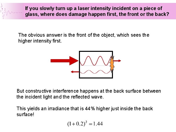
If you slowly turn up a laser intensity incident on a piece of glass, where does damage happen first, the front or the back? The obvious answer is the front of the object, which sees the higher intensity first. But constructive interference happens at the back surface between the incident light and the reflected wave. This yields an irradiance that is 44% higher just inside the back surface!
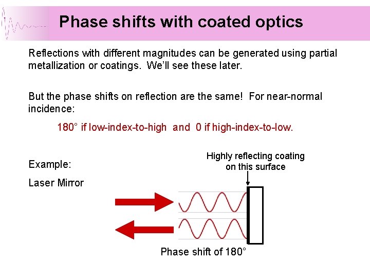
Phase shifts with coated optics Reflections with different magnitudes can be generated using partial metallization or coatings. We’ll see these later. But the phase shifts on reflection are the same! For near-normal incidence: 180° if low-index-to-high and 0 if high-index-to-low. Example: Highly reflecting coating on this surface Laser Mirror Phase shift of 180°
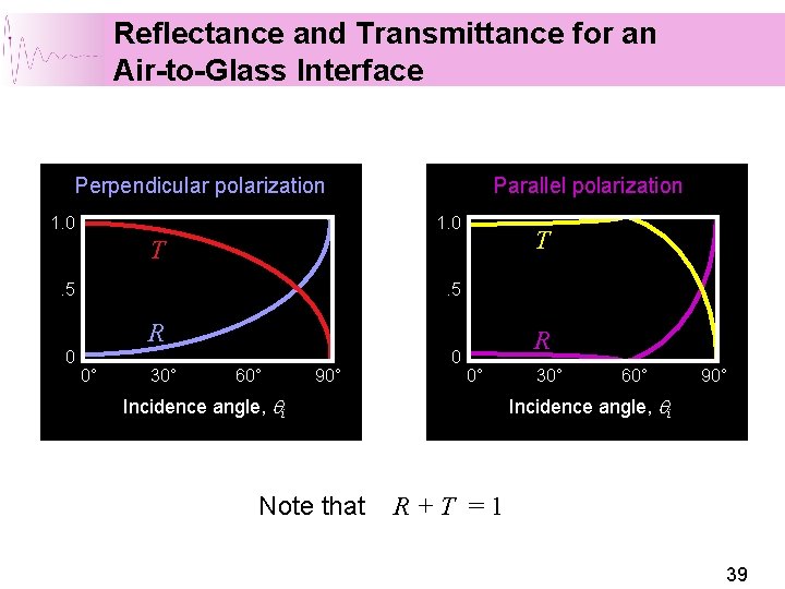
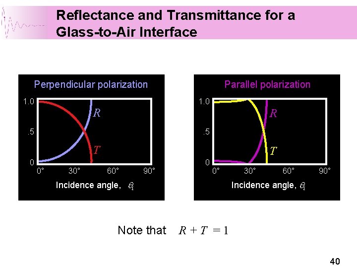
Transmittance and Reflectance We hebben de Fresnel coëfficiënten afgeleid verhoudingen Amplitudes. Hoe zit het met het VERMOGEN? 36
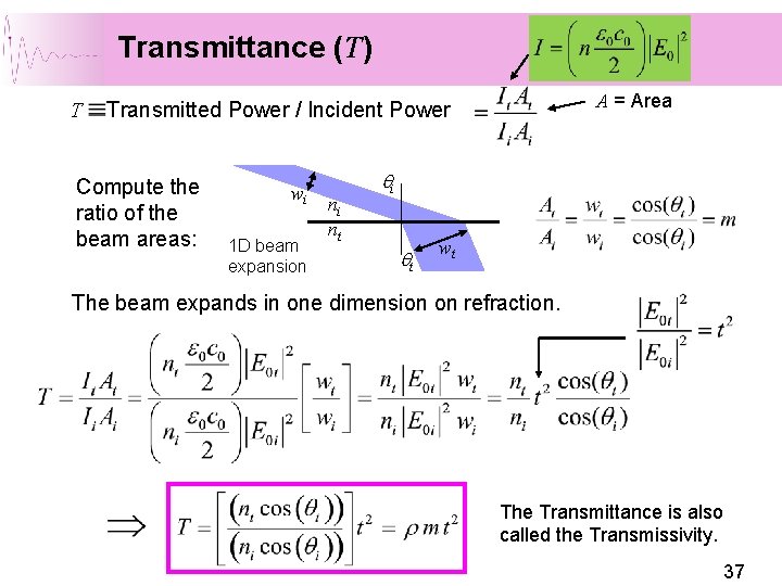
Transmittance (T) T A = Area Transmitted Power / Incident Power Compute the ratio of the beam areas: wi 1 D beam expansion ni nt qi qt wt The beam expands in one dimension on refraction. The Transmittance is also called the Transmissivity. 37
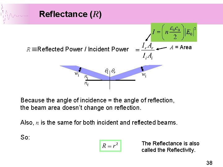
Reflectance (R) R A = Area Reflected Power / Incident Power wi ni nt qi qr wi Because the angle of incidence = the angle of reflection, the beam area doesn’t change on reflection. Also, n is the same for both incident and reflected beams. So: The Reflectance is also called the Reflectivity. 38
Reflectance and Transmittance for an Air-to-Glass Interface Perpendicular polarization 1. 0 Parallel polarization 1. 0 T T. 5 R 0 0° 30° 60° 90° 0 R 0° Incidence angle, qi Note that 30° 60° 90° Incidence angle, qi R+T =1 39
Reflectance and Transmittance for a Glass-to-Air Interface Perpendicular polarization 1. 0 Parallel polarization 1. 0 R R . 5 T 0 0° 30° T 60° 90° 0 0° Incidence angle, qi Note that 30° 60° 90° Incidence angle, qi R+T =1 40
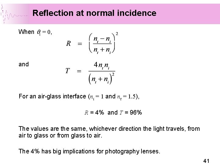
Reflection at normal incidence When qi = 0, and For an air-glass interface (ni = 1 and nt = 1. 5), R = 4% and T = 96% The values are the same, whichever direction the light travels, from air to glass or from glass to air. The 4% has big implications for photography lenses. 41
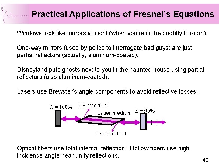
Practical Applications of Fresnel’s Equations Windows look like mirrors at night (when you’re in the brightly lit room) One-way mirrors (used by police to interrogate bad guys) are just partial reflectors (actually, aluminum-coated). Disneyland puts ghosts next to you in the haunted house using partial reflectors (also aluminum-coated). Lasers use Brewster’s angle components to avoid reflective losses: R = 100% 0% reflection! Laser medium R = 90% 0% reflection! Optical fibers use total internal reflection. Hollow fibers use highincidence-angle near-unity reflections. 42
The critical angle and beyond Reflection coefficient, r 1. 0 Critical angle r ┴ 0 -1. 0 • • Total internal reflection Brewster’s angle Critical angle 0° r|| 30° 60° Incidence angle, θ i 90° Totale Interne Reflectie Evanescent Waves 43
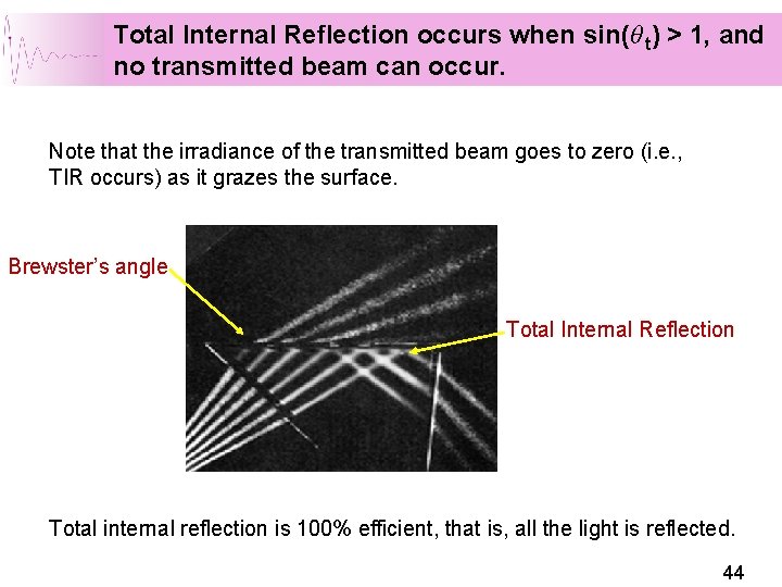
Total Internal Reflection occurs when sin(θ t) > 1, and no transmitted beam can occur. Note that the irradiance of the transmitted beam goes to zero (i. e. , TIR occurs) as it grazes the surface. Brewster’s angle Total Internal Reflection Total internal reflection is 100% efficient, that is, all the light is reflected. 44
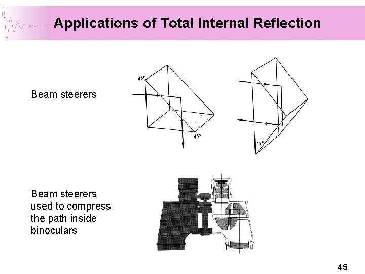
Applications of Total Internal Reflection Beam steerers used to compress the path inside binoculars 45
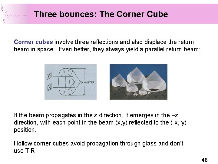
Three bounces: The Corner Cube Corner cubes involve three reflections and also displace the return beam in space. Even better, they always yield a parallel return beam: If the beam propagates in the z direction, it emerges in the –z direction, with each point in the beam (x, y) reflected to the (-x, -y) position. Hollow corner cubes avoid propagation through glass and don’t use TIR. 46
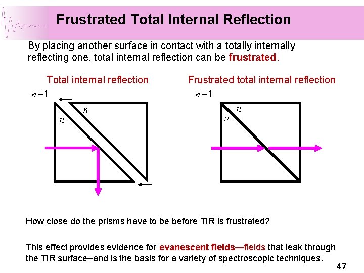
Frustrated Total Internal Reflection By placing another surface in contact with a totally internally reflecting one, total internal reflection can be frustrated. Total internal reflection n=1 n n Frustrated total internal reflection n=1 n n How close do the prisms have to be before TIR is frustrated? This effect provides evidence for evanescent fields—fields that leak through the TIR surface–and is the basis for a variety of spectroscopic techniques. 47
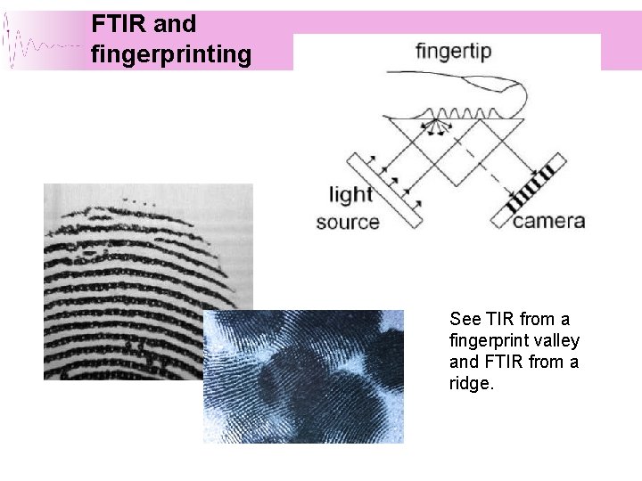
FTIR and fingerprinting See TIR from a fingerprint valley and FTIR from a ridge.
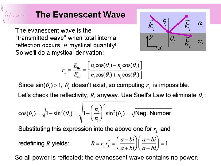
The Evanescent Wave The evanescent wave is the "transmitted wave" when total internal reflection occurs. A mystical quantity! So we'll do a mystical derivation: qi y x ni qt nt
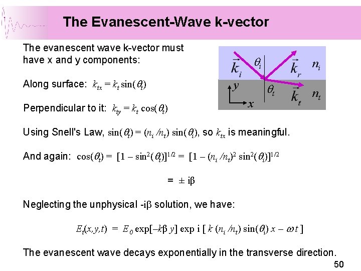
The Evanescent-Wave k-vector The evanescent wave k-vector must have x and y components: Along surface: ktx = kt sin(qt) qi y Perpendicular to it: kty = kt cos(qt) x ni qt nt Using Snell's Law, sin(qt) = (ni /nt) sin(qi), so ktx is meaningful. And again: cos(qt) = [1 – sin 2(qt)]1/2 = [1 – (ni /nt)2 sin 2(qi)]1/2 = ± iβ Neglecting the unphysical -ib solution, we have: Et(x, y, t) = E 0 exp[–kβ y] exp i [ k (ni /nt) sin(qi) x – w t ] The evanescent wave decays exponentially in the transverse direction. 50
Fermat’s principle: Light travels shortest path in time Possible path from S to P reflected from a mirror Amplitude and phase in complex plane for each path 51
The End 52