Interfaces and Synchronization Martin Weiss EIA 232 D
- Slides: 23
Interfaces and Synchronization Martin Weiss
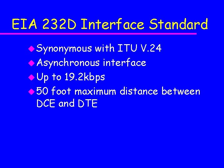
EIA 232 D Interface Standard u Synonymous with ITU V. 24 u Asynchronous interface u Up to 19. 2 kbps u 50 foot maximum distance between DCE and DTE
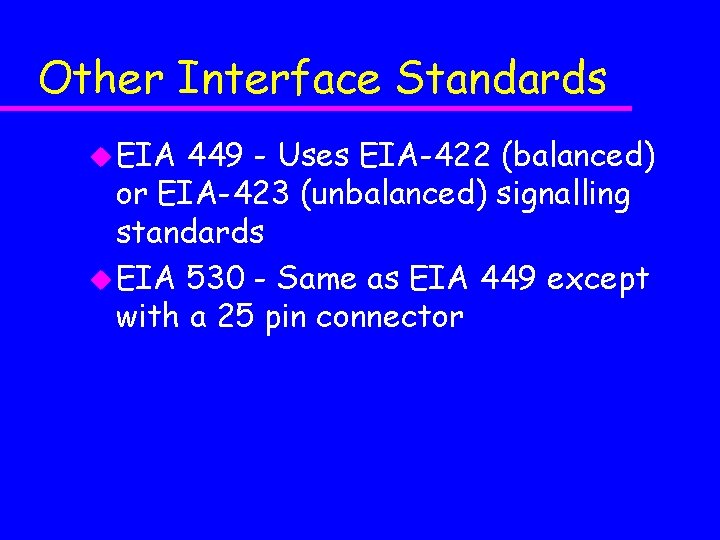
Other Interface Standards u EIA 449 - Uses EIA-422 (balanced) or EIA-423 (unbalanced) signalling standards u EIA 530 - Same as EIA 449 except with a 25 pin connector
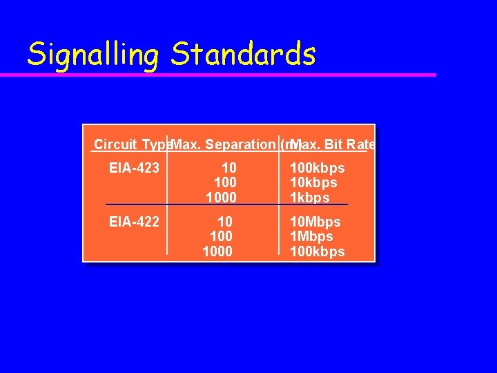
Signalling Standards Circuit Type. Max. Separation (m) Max. Bit Rate EIA-423 10 1000 100 kbps 1 kbps EIA-422 10 1000 10 Mbps 100 kbps
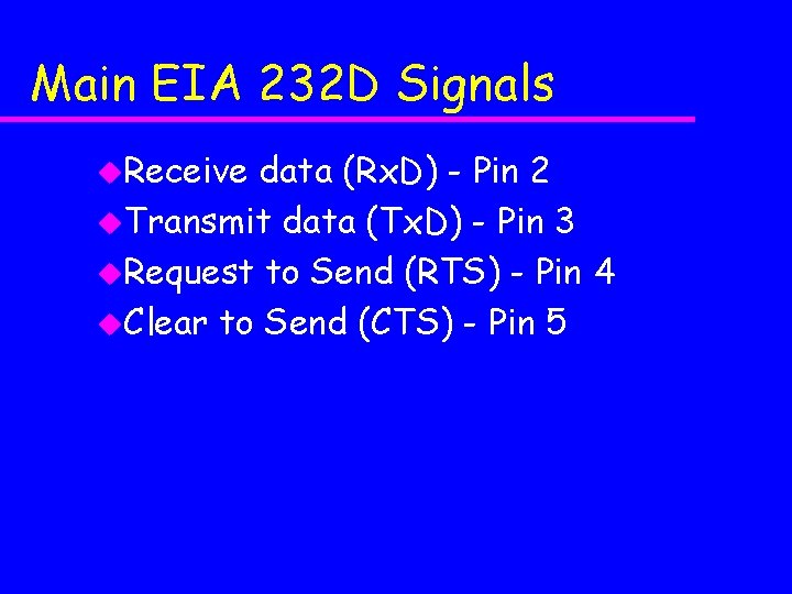
Main EIA 232 D Signals u. Receive data (Rx. D) - Pin 2 u. Transmit data (Tx. D) - Pin 3 u. Request to Send (RTS) - Pin 4 u. Clear to Send (CTS) - Pin 5
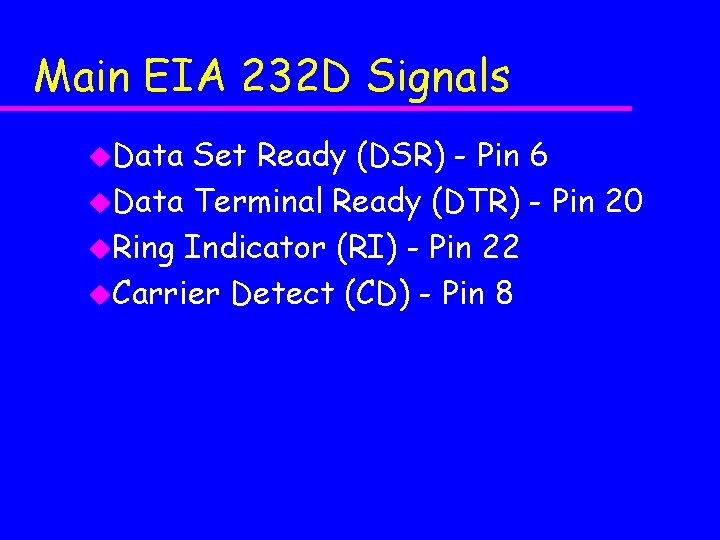
Main EIA 232 D Signals u. Data Set Ready (DSR) - Pin 6 u. Data Terminal Ready (DTR) - Pin 20 u. Ring Indicator (RI) - Pin 22 u. Carrier Detect (CD) - Pin 8
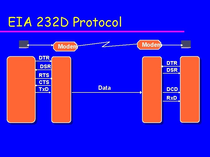
EIA 232 D Protocol Modem DTR DSR RTS CTS Tx. D Data DCD Rx. D
Questions u For data transfer, when would we want to transfer bits one at a time, and when as a group? u Why do we have to worry about synchronization? u How can we begin to quantify performance issues?
Bit Synchronization u. The receiver must know when a bit starts and when it stops u. Normally, synchronization sequences are necessary
Character Synchronization u. When does a character start?
Asynchronous Communications u. Characters are transmitted when they are generated u. The receiver must be configured so that the gross transmission characteristics are identical to the transmitter
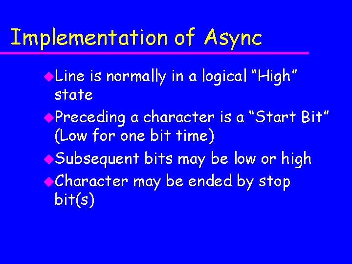
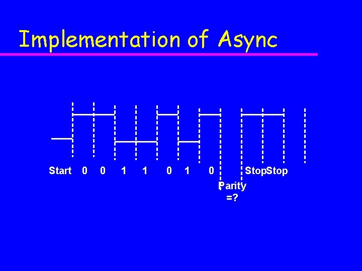
Implementation of Async u. Line is normally in a logical “High” state u. Preceding a character is a “Start Bit” (Low for one bit time) u. Subsequent bits may be low or high u. Character may be ended by stop bit(s)
Implementation of Async Start 0 0 1 1 0 Stop Parity =?
Discussion of Async u. Very simple to implement u. Inefficient u. Alternative: synchronous transmission
Discussion of Async
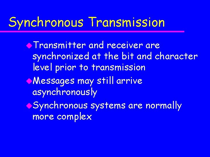
Synchronous Transmission u. Transmitter and receiver are synchronized at the bit and character level prior to transmission u. Messages may still arrive asynchronously u. Synchronous systems are normally more complex
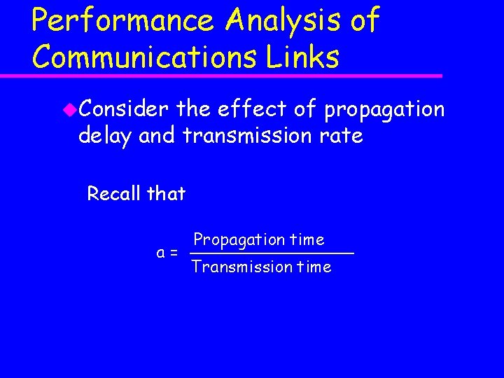
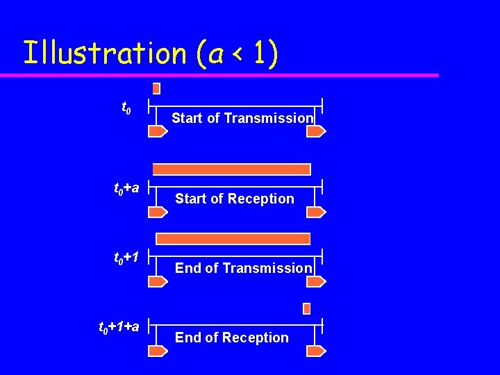
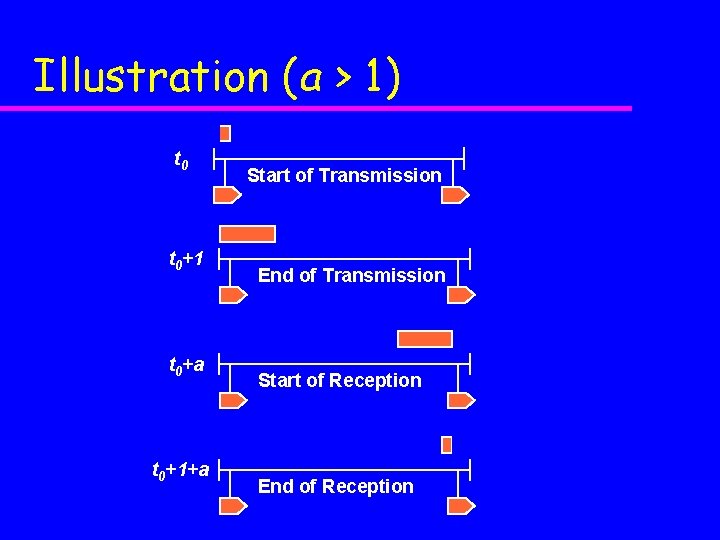
Performance Analysis of Communications Links u. Consider the effect of propagation delay and transmission rate Recall that a= Propagation time Transmission time
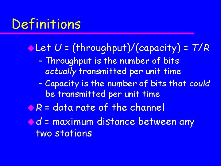
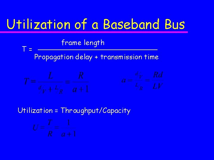
Definitions u Let U = (throughput)/(capacity) = T/R – Throughput is the number of bits actually transmitted per unit time – Capacity is the number of bits that could be transmitted per unit time u. R = data rate of the channel u d = maximum distance between any two stations
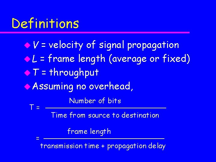
Definitions u. V = velocity of signal propagation u L = frame length (average or fixed) u T = throughput u Assuming no overhead, T= = Number of bits Time from source to destination frame length transmission time + propagation delay
Illustration (a < 1) t 0+a t 0+1+a Start of Transmission Start of Reception End of Transmission End of Reception
Illustration (a > 1) t 0+1 t 0+a t 0+1+a Start of Transmission End of Transmission Start of Reception End of Reception
Utilization of a Baseband Bus T= frame length Propagation delay + transmission time Utilization = Throughput/Capacity
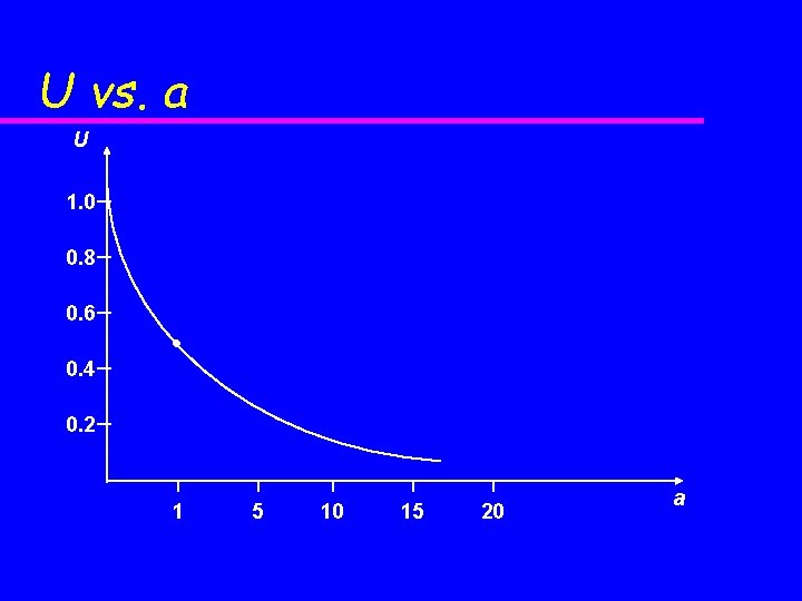
U vs. a U 1. 0 0. 8 0. 6 0. 4 0. 2 1 5 10 15 20 a