Impressions of CARMALS J Kissel for the people


![The LIGO Arm Cavity Problem Laser frequency = 3 [THz] = 3 e 14 The LIGO Arm Cavity Problem Laser frequency = 3 [THz] = 3 e 14](https://slidetodoc.com/presentation_image/1c7984ffe53b5b3b6f3f1a05db4e1993/image-6.jpg)


- Slides: 33

Impressions of CARM/ALS J. Kissel, for the people way smarter than me. G 1400519 -v 3 1

Primer The development of CARM/ALS spans many decades, many people, and many subsystems, so documentation isn’t always consistent and it’s tough to find the big picture with everything included in one place. This is my attempt. • I’m *still* getting to know the subsystem • This presentation will not be perfect • Go to references (Related Documents on DCC file card) for further reading, they’ve done a better job at some of the details. • This is now a “course” meant to be taught over a few days, so forgive its length G 1400519 -v 3 Thanks for your patience. 2

Intro to Cavity “Locking” Optical Isolator Laser Reflected Power High Finesse G 1400519 -v 3 Low Finesse Resonant cavity resonates, when cavity length is an integer number of laser wavelengths More reflective mirrors = Tighter resonance condition Equivalent noise sources to this system: cavity length changes or laser frequency/wavelength changes On Resonance Free Spectral Range DL = L �� ____ Df c 3

Robert V. Pound Ron W P Drever John L Hall Intro to PDH Faraday Isolator Phase / Frequency Modulator Optical Isolator Locks laser frequency to resonant cavity, following the length of the cavity as it changes Laser Control Filter “Servo” Local Oscillator (LO) Phase Delay Reflected Field Power Reflected Field Phase Mixer/ Low-Pass Filter “Demodulator” “Lock acquisition” or “catch (and hold) lock” = Length changes slower than the control bandwidth Control servo holds the laser frequency within linear operating regime G 1400519 -v 3 PDH Error Signal Non-linear in regions outside cavity linewidth 4

Intro to PDH Faraday Isolator Phase / Frequency Modulator Optical Isolator Laser Local Oscillator (LO) Control Filter “Servo” Phase Delay Low-Pass Filter Df = l ___ c. L Cavity treated as “frequency reference” Mixer DL See Appendix A for more Essential Cavity Eqs. G 1400519 -v 3 PDH locking the Laser to Cavity reduces frequency noise The LONGER the cavity, and/or the SMALLER the length changes, the better the frequency reference, the lower the frequency noise 5
![The LIGO Arm Cavity Problem Laser frequency 3 THz 3 e 14 The LIGO Arm Cavity Problem Laser frequency = 3 [THz] = 3 e 14](https://slidetodoc.com/presentation_image/1c7984ffe53b5b3b6f3f1a05db4e1993/image-6.jpg)
The LIGO Arm Cavity Problem Laser frequency = 3 [THz] = 3 e 14 [Hz] Standard Nd: YAG laser frequency noise at ~10 -100 Hz = 1 e 4 [Hz/rt. Hz] Highly reflective mirrors Long light storage time High finesse Great for gravitational wave detection a. LIGO Needs frequency stabilization at ~10 -100 Hz = 1 e-6 [Hz/rt. Hz] level! (in loop) Needs 10 orders of magnitude of frequency noise suppression! G 1400519 -v 3 Highly reflective mirrors Very small / tight cavity line width: FWHM ≈ 100 [Hz] ≈ 1 [nm] Difficult to catch a resonance condition In order to merge corner station with arms during lock acquisition, while building up frequency stability, we need *LOTS* of loops. 6

LIGO = PDH to the MAX SIX nested / interconnected PDH loops to control the laser frequency: FSS IMC PDH Fiber PLL ALS PDH ALS COMM CARM G 1400519 -v 3 7

Frequency Actuators on Light AOMs vs. EOMs Acousto-Optic Modulator • Bragg Crystal acoustically excited by PZT • Diffraction light frequency is Doppler shifted to f -> f + m F where m is the diffraction order and F is excitation frequency Electro-Optic Modulator • Creates sidebands via phase modulation via Pockels effect • Refractive index is a function of the electric field • Output phase proportional to how much time in crystal • Change electric field, change refractive index, change the phase of light. m=+2 m=+1 m=0 m=-1 G 1400519 -v 3 m=-2 A eiwt -> A eiwt+i G sin(Wt) ~A eiwt (1 + i G sin(Wt) + …) (for small G) sin(x) = (1/2 i) e+ix –e-ix = A eiwt (1 + G/2 e+i. Wt - G/2 e-i. Wt + …) = A (eiwt + G/2 e+i(w+W)t - G/2 e+i(w-W)t + …) 8

FSS IMC PDH Fiber PLL ALS PDH ALS COMM ALS DIFF G 1400519 -v 3 Frequency Stabilization Servo Just a fancy PDH loop! Light sent into Reference Cavity serving as an external frequency reference - L ≈ 0. 5 [m] - In a vacuum can on the PSL Photo-diode demodulated at 21. 5 [MHz], low passed, and control filtered, and sent to laser Low Frequency = “Slow” = laser temperature High Frequency = “Fast” = Laser cavity length • EOM adds 21. 5 MHz sidebands for PDH locking the laser to the reference cavity • AOM shifts the picked-off laser frequency up by +80 upon first pass and then another +80 upon second • Voltage-Controlled Oscillator (VCO) provides adjustable local oscillator (LO) frequency at 80 +/ - 1 [MHz], so we can adjust the main PSL carrier frequency. 9

FSS IMC PDH Fiber PLL ALS PDH ALS COMM ALS DIFF Input Mode Cleaner PDH Just a fancy PDH loop! (but now nested with FSS) Now 16 [m], suspended input mode cleaner cavity serves as frequency reference EOM for IMC oscillator is set at 24 [MHz] - Fast control sent as control input PSL VCO (remember the +/- 1 [MHz]? ), adjusting the carrier frequency to follow the IMC’s stable reference G 1400519 -v 3 - Slow control sent to IMC cavity length (because VCO doesn’t have the low-frequency range for HAM 2 HAM 3 differential motion) 10

FSS IMC PDH Fiber PLL ALS PDH ALS COMM ALS DIFF PSL / End-Station Laser Phase-Locking Loop MEANWHILE!!! Begin to prep the arms for merging with the red… • • • G 1400519 -v 3 Take the *transmitted* light from Reference Cavity, feed it into a optical fiber (on the PSL), down-shift back to 0 [MHz] with fiber AOM (in the PSL racks) Ship to end stations (via optical fiber), Phase lock the carrier of an independent, RED / GREEN auxiliary laser to PSL fiber transmission • Catch PSL / Aux RED beat note on PD, a send to a phasefrequency detector as the mixer, demodulate at ~40 [Hz] with VCO • Laser / PLL forces aux laser to have a RED, 1064 nm carrier +/-40 [MHz], therefore GREEN, 532 nm carrier +/- 80 [MHz] in GREEN • - for X arm, + for Y arm Phase-Locking Loop = PLL 11

IMC PDH Fiber PLL ALS PDH ALS COMM ALS DIFF FIND IR Arm Length Stabilization PDH Just a fancy PDH loop! (Now nested with Fiber PLL) Now back to standard PDH locking of arm with green Send fast feed back to end-VCO … just like IMC Send slow feed back to arm cavity length … just like IMC G 1400519 -v 3 12

Fiber PLL ALS PDH ALS COMM ALS DIFF FIND IR IR FOUND PSL / Common Arm Stabilization Now we nest the green and red frequency, starting to sync the PSL to the arms. • • • Transmitted green from X arm is steered to combine with a pick-off of the PSL, frequency-doubled (turning RED to GREEN) via second harmonic generator (SHG). That beat note (-80 [MHz]), is fed into another PLL / VCO combination The control signal is fed into a summing node, which cascades down to the IMC, then to the PSL (or IMC) This is sometimes called an “additive offset” because you’re adding the ARM offset to the laser frequency to the IMC control, which is already offsetting the carrier G 1400519 -v 3 13

ALS PDH ALS COMM ALS DIFF FIND IR IR FOUND ARMS OFF REZ Differential Arm Length Stabilization Now compare the X arm transmitted green light against the Y arm, using the beat note (160 [MHz]) as the first sensitive measure of DARM Unlike COMM, DIFF is digitized and send to ETMs for control We usually control DIFF by just pushing on one arm G 1400519 -v 3 14

ALS PDH ALS COMM ALS DIFF FIND IR IR FOUND ARMS OFF REZ The Rest of the Lock Acquisition Sequence • From here, we have the arms controlled, but at this point the frequency control is no where near good enough, and we don’t have DRMI locked. • The next MANY steps are all in place such that we can lock DRMI independently, then slowly bring the arms into resonance with DRMI. • It’s a convoluted process that involves slowly/carefully switching between equivalent sensors and actuators, but going from high noise / high range to low noise / low range. Let’s go! G 1400519 -v 3 15

FIND IR ALS COMM ALS DIFF FIND IR IR FOUND ARMS OFF REZ DRMI Steer around COMM then DIFF frequency control (via slow digital control of COMM then DIFF VCO frequencies, which in turn pushes around the PSL frequency), to find what frequency resonates in the arms Whether arms are resonant or not is measured by the RED transmitted power on the transmon platform G 1400519 -v 3 16

ALS DIFF FIND IR IR FOUND ARMS OFF REZ DRMI CARM ON TR G 1400519 -v 3 IR FOUND Congrats! Now we know at what carrier frequency we should operate the PSL such that IR will resonate in the arms. 17

FIND IR IR FOUND ARMS OFF REZ DRMI CARM ON TR DARM TO RF G 1400519 -v 3 ARMS OFF RESONANCE Here, we then intentionally add an OFFSET to the ALS DIFF and COMM loops to push the arms off resonance, so we can lock DRMI without the interference of the arms 18

IR FOUND ARMS OFF REZ DRMI CARM ON TR DARM TO RF CARM TO REFL G 1400519 -v 3 DRMI (1 F, 3 F) In this step, we use the temporary sensors, REFL AIR (shown) and AS AIR (not shown) to lock PRCL, MICH, and SCRL (a. k. a DRMI) on first on “ 1 f” (9 and 45 MHz), then temporarily switch to an harmonic of the modulation frequency (“ 3 f”) that won’t be confused when the arms come back into resonance 19

IR FOUND ARMS OFF REZ DRMI CARM ON TR DARM TO RF CARM TO REFL An aside: Why 1 f vs 3 f DRMI? I lied to you a bit on slide 8 when I said A eiwt -> A eiwt+i G sin(Wt) ~A eiwt (1 + i G sin(Wt) + …) (for small G) sin(x) = (1/2 i) e+ix –e-ix = A eiwt (1 + G/2 e+i. Wt - G/2 e-i. Wt) = A (eiwt + G/2 e+i(w+W)t - G/2 e+i(w-W)t) To be more complete… And that’s the electric field. Photodetectors measure power (=|field|2), so there will be cross-terms as well… A eiwt -> A eiwt+i G sin(Wt) = A eiwt Sk [ Jk(G) eik. Wt ] Jk(G) ~ 1/k! (G/2)k (for small G) J-k(G) = - Jk(G) = A eiwt (… - G/6 e-i 3 Wt - G/4 e-i 2 Wt - G/2 e-i. Wt + 1 + G/2 e+i. Wt + G/4 e-i 2 Wt + G/6 e-i 3 Wt + … ) 9, (2*9)=18, (2*9 -45) = 27, (9 -45)=36, 45, etc. … one modulation frequency yields lots of harmonics: G 1400519 -v 3 The RF response of our LSC photodetectors 20

IR FOUND ARMS OFF REZ DRMI CARM ON TR DARM TO RF CARM TO REFL An aside: Why 1 f vs 3 f DRMI? Arai, Koji, et al. Phys. Lett A 273. 1 -2 (2000): 15 -24. 3 f signals are inherently better than 1 f signals at distinguishing d. L+ (CARM) from dl+ (PRCL) a. LIGO Schnupp Asymmetry As we reduce the CARM offset (bring the arms into resonance), 3 f signals are much less effected, and don’t flip sign, unlike 1 f signals! G 1400519 -v 3 21

IR FOUND ARMS OFF REZ DRMI CARM ON TR DARM TO RF CARM TO REFL G 1400519 -v 3 DRMI (1 F, 3 F) Back to the acquisition sequence… We leave this slide with DRMI on 3 f, and CARM held off resonance with ALS COMM 22

ARMS OFF REZ DRMI CARM ON TR DARM TO RF CARM TO REFL RESONANCE CARM ON TRANSMISSION OK, so we’ve got DRMI on 3 f so it’s ”insensitive” to CARM, so let’s reduce the offset (and improve the sensor as we go) … First, bring the arms in a bit, and use the transmitted light from the arms as our first better sensor CARM_150_PICOMETERS… G 1400519 -v 3 23

DRMI CARM ON TR DARM TO RF CARM TO REFL RESONANCE DRMI ON POP DARM to RF OK, this talk admittedly ignores the anti-symmetric port (DARM, MICH, and SRCL) but there’s an in-air RFPD there (AS AIR) that can be used to measure DARM with IR, digitized PDH scheme that’s more sensitive, so we switch from DIFF to RF DARM here. CARM_5_PICOMETERS… G 1400519 -v 3 24

CARM ON TR DARM TO RF CARM TO REFL RESONANCE DRMI ON POP PARK ALS VCO CARM to REFL While we continue to reduce the CARM offset, we switch CARM control from the combo of arm transmissions to a digitized RF PDH scheme with an in-air RFPD at the REFL port still not good enough frequency noise, though… G 1400519 -v 3 25

DARM TO RF CARM TO REFL RESONANCE DRMI ON POP PARK ALS VCO SHUTTER ALS G 1400519 -v 3 RESONANCE Huzzah! The CARM DOF is now completely resonant, no longer detuned by our intentional offset! We also switch to our control of CARM to completely analog, such that we can increase the bandwidth of our loop to ~20 k. Hz 26

DARM TO RF CARM TO REFL RESONANCE DRMI ON POP PARK ALS VCO SHUTTER ALS (and we’re also beginning to shut off the ALS system) G 1400519 -v 3 DRMI ON POP Lastly, but not leastly, we switch control of DRMI to the in-vac RFPD called POP (Pick. Off port of the Power recycling cavity) for further improved DRMI noise 27

DARM TO RF CARM TO REFL RESONANCE DRMI ON POP PARK ALS VCO SHUTTER ALS PARK ALS VCO Now, since we’re no longer using them, we drive a hard offset into the ALS VCOs to “park” them at a frequency so they don’t wander around and interfere with the IMC’s IR VCO (>> CARM >> DARM) Whistle glitches anyone? G 1400519 -v 3 No thank you! 28

DARM TO RF CARM TO REFL RESONANCE DRMI ON POP PARK ALS VCO SHUTTER ALS And here, at the final stages of the CARM portion of the lock acquisition sequence, we use remote mirror / dump flippers to completely block green light from entering into the arms. Goodnight moo… *AHEM* green G 1400519 -v 3 29

Now You Understand this Diagram Congratulations! G 1400519 -v 3 30

The Nested Loop Topology for Frequency Stabilization From Evan Hall’s Thesis P 1600295 A(f) = The IMC PDH control filter and requested voltage control to the AOM frequency before the reference cavity F(f) = The “Fast” CARM path to PDH control a. k. a. “Additive offset” path G(f) = Reference cavity control over PSL frequency, a. k. a the FSS K(f) = The IMC (and MC REFL PD) Response to Frequency/Length changes M(f) = The “Slow” CARM path to Control IMC Length and the corresponding frequency change T(f) = Very slow Tidal control fed directly to the ETMs *** We didn’t talk about this. See T 1400733. G 1400519 -v 3 P(f) = The interferometer’s CARM degree of freedom (and the REFL PD that measures it) Response to Frequency/ Length changes 31

The Nested Loop Open Loop Gain TFs From Evan Hall’s Thesis P 1600295 CARM OLG TF IMC OLG TF 15, 000 Hz UGF x 1 e 3 at 100 Hz 30, 000 Hz UGF x 1 e 4 at 100 Hz FSS OLG TF 300, 000 Hz UGF x 1 e 3 at 100 Hz = 10 orders of magnitude 100 Hz G 1400519 -v 3 32

Appendix to PDH (Essential Cavity Equations) Cavity Resonance Condition Integer Number of Wavelengths fit inside length of the cavity Phase <-> Length <-> Frequency Free Spectral Range (distance / frequency spacing between resonances) c ___ FSR = D f = (in [Hz]) 2 L ** 2 l ___ FSR = D l = 2 L (in [m]) Cavity Linewidth = “Full-width Half Maximum” = 2* Cavity Pole Frequency (in [Hz]) Cavity Finesse _____ ** Check out P 010013 for why this is an approximation p FSR p √ r 1 r 2 p ___________ ______ �� = = ≈ ≈ (dimensionless) 1 – r r 1 – r 1 r 2 1 2 FWHM 1 – r 1 r 2 _____ 2 arcsin ______ 2 √ r 1 r 2 G 1400519 -v 3 As mirror reflectivities go up, cavity Finesse, �� , goes up, Linewidth gets smaller ( 33
 Kensington kissel
 Indentation tool marks
 Carmals
 Carmals
 Impressions of feelings
 Nerve supply of spleen
 Reading impressions
 True or false
 First impression vocabulary
 Dental impressions course
 Radiant impressions custom breast prosthesis
 Tyre impression forensic science
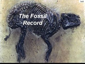
 Evidence of evolution of remnants and impressions *
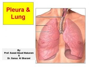
 Mediastinal surface
 What are your first impressions of beowulf?
 Are impressions left by friction ridge skin on a surface
 Abrasion marks are made by objects which include
 First impressions
 Liver diaphragmatic surface
 Tool impressions
 4.05 quiz: footwear and tire marks
 Some factors that personalize our footwear include:
 Types of impressions
 First impressions count job interview
 Convert impressions to grps
 Nerve supply of pleura
 Examples of dominant impressions
 Success dress to win
 1. describe xpresso lube's service package
 Looking out looking in summary
 Academic impressions
 Rifled barrel
 First impressions finger print
 Literacy narrative essay examples

