Imaging of Microwave Currents and Microscopic Sources of



- Slides: 23
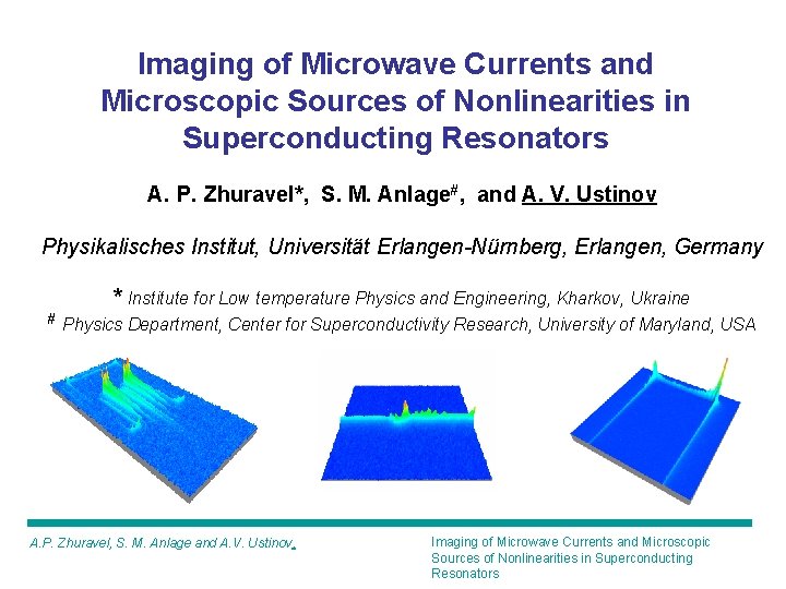
Imaging of Microwave Currents and Microscopic Sources of Nonlinearities in Superconducting Resonators A. P. Zhuravel*, S. M. Anlage#, and A. V. Ustinov Physikalisches Institut, Universität Erlangen-Nürnberg, Erlangen, Germany * Institute for Low temperature Physics and Engineering, Kharkov, Ukraine # Physics Department, Center for Superconductivity Research, University of Maryland, USA A. P. Zhuravel, S. M. Anlage and A. V. Ustinov, Imaging of Microwave Currents and Microscopic Sources of Nonlinearities in Superconducting Resonators
Motivation / Goals To image rf currents in operating superconducting microwave circuits and devices To identify sources of microwave nonlinearities in superconductors To investigate how rf currents are redistributed by mm- and nmscale defects To develop new methods to investigate microwave nonlinearities in superconductors A. P. Zhuravel, S. M. Anlage and A. V. Ustinov, Imaging of Microwave Currents and Microscopic Sources of Nonlinearities in Superconducting Resonators
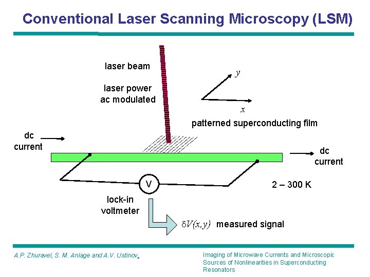
Conventional Laser Scanning Microscopy (LSM) laser beam laser power ac modulated y x patterned superconducting film dc current V 2 – 300 K lock-in voltmeter d. V(x, y) measured signal A. P. Zhuravel, S. M. Anlage and A. V. Ustinov, Imaging of Microwave Currents and Microscopic Sources of Nonlinearities in Superconducting Resonators
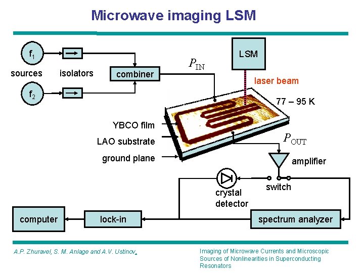
Microwave imaging LSM f 1 sources isolators combiner PIN LSM laser beam f 2 77 – 95 K YBCO film POUT LAO substrate ground plane amplifier crystal detector computer lock-in A. P. Zhuravel, S. M. Anlage and A. V. Ustinov, switch spectrum analyzer Imaging of Microwave Currents and Microscopic Sources of Nonlinearities in Superconducting Resonators
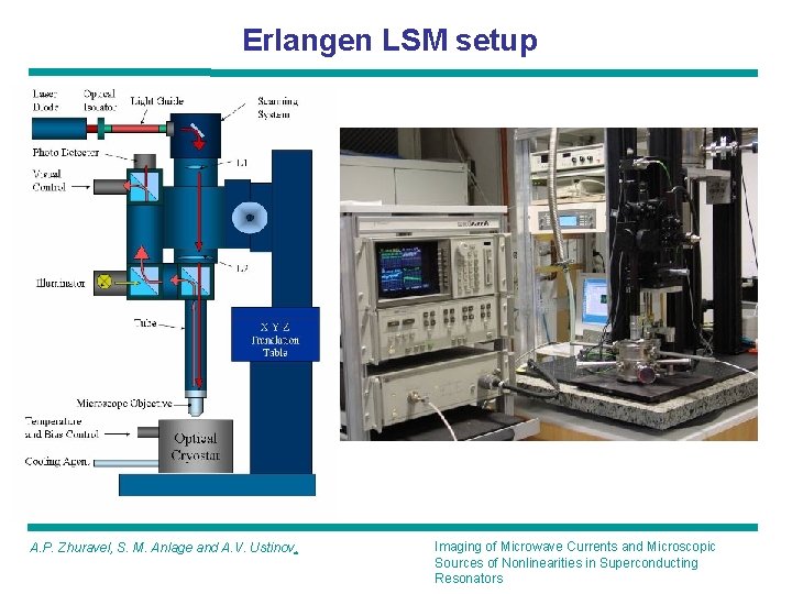
Erlangen LSM setup A. P. Zhuravel, S. M. Anlage and A. V. Ustinov, Imaging of Microwave Currents and Microscopic Sources of Nonlinearities in Superconducting Resonators
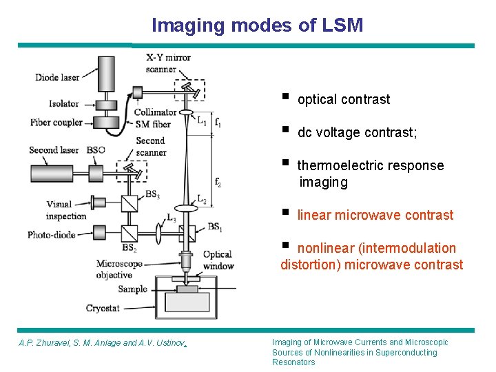
Imaging modes of LSM § optical contrast § dc voltage contrast; § thermoelectric response imaging § linear microwave contrast § nonlinear (intermodulation distortion) microwave contrast A. P. Zhuravel, S. M. Anlage and A. V. Ustinov, Imaging of Microwave Currents and Microscopic Sources of Nonlinearities in Superconducting Resonators
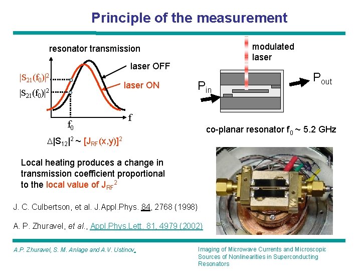
Principle of the measurement modulated laser resonator transmission laser OFF |S 21(f 0)|2 laser ON |S 21(f 0)|2 f 0 Pin Pout f co-planar resonator f 0 ~ 5. 2 GHz D|S 12|2 ~ [JRF(x, y)]2 Local heating produces a change in transmission coefficient proportional to the local value of JRF 2 J. C. Culbertson, et al. J. Appl. Phys. 84, 2768 (1998) A. P. Zhuravel, et al. , Appl. Phys. Lett. 81, 4979 (2002) A. P. Zhuravel, S. M. Anlage and A. V. Ustinov, Imaging of Microwave Currents and Microscopic Sources of Nonlinearities in Superconducting Resonators
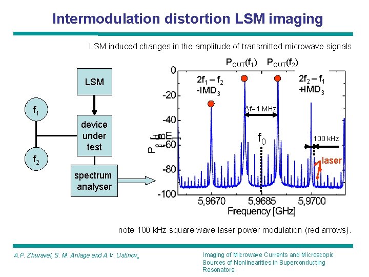
Intermodulation distortion LSM imaging LSM induced changes in the amplitude of transmitted microwave signals POUT(f 1) POUT(f 2) 2 f 2 – f 1 +IMD 3 2 f 1 – f 2 -IMD 3 LSM Df=1 MHz f 1 device under test f 0 f 2 100 k. Hz laser spectrum analyser note 100 k. Hz square wave laser power modulation (red arrows). A. P. Zhuravel, S. M. Anlage and A. V. Ustinov, Imaging of Microwave Currents and Microscopic Sources of Nonlinearities in Superconducting Resonators
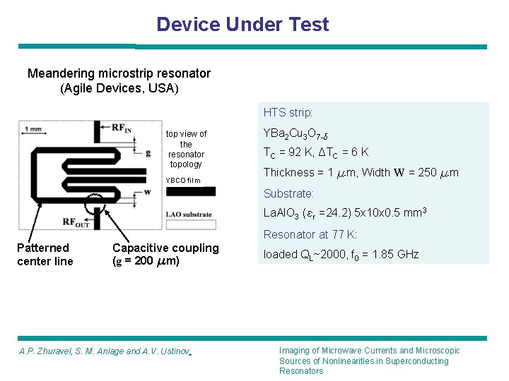
Device Under Test Meandering microstrip resonator (Agile Devices, USA) HTS strip: top view of the resonator topology YBCO film YBa 2 Cu 3 O 7 -d TC = 92 K, DTC = 6 K Thickness = 1 mm, Width W = 250 mm Substrate: La. Al. O 3 (er =24. 2) 5 x 10 x 0. 5 mm 3 Resonator at 77 K: Patterned center line Capacitive coupling (g = 200 mm) A. P. Zhuravel, S. M. Anlage and A. V. Ustinov, loaded QL~2000, f 0 = 1. 85 GHz Imaging of Microwave Currents and Microscopic Sources of Nonlinearities in Superconducting Resonators
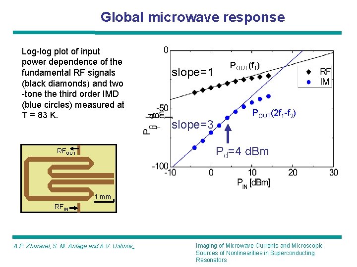
Global microwave response Log-log plot of input power dependence of the fundamental RF signals (black diamonds) and two -tone third order IMD (blue circles) measured at T = 83 K. slope=1 slope=3 POUT(f 1) POUT(2 f 1 -f 2) Pd=4 d. Bm RFOUT 1 mm RFIN A. P. Zhuravel, S. M. Anlage and A. V. Ustinov, Imaging of Microwave Currents and Microscopic Sources of Nonlinearities in Superconducting Resonators
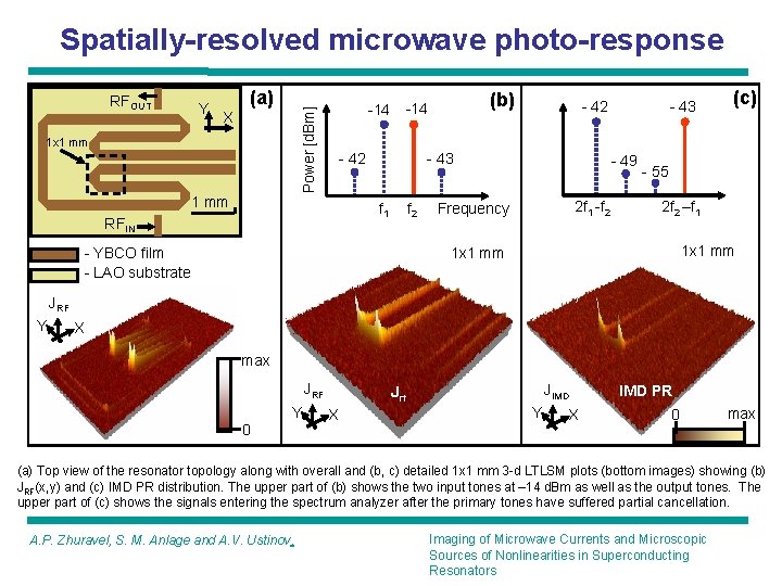
Spatially-resolved microwave photo-response Y (a) Power [d. Bm] RFOUT X 1 x 1 mm -14 - 42 - 43 f 1 RFIN (b) -14 f 2 - YBCO film - LAO substrate - 49 2 f 1 -f 2 Frequency (c) - 55 2 f 2 –f 1 1 x 1 mm x y JRF Y - 43 X max JRF Y 0 JIMD Jrf X Y X IMD PR 0 max (a) Top view of the resonator topology along with overall and (b, c) detailed 1 x 1 mm 3 -d LTLSM plots (bottom images) showing (b) JRF(x, y) and (c) IMD PR distribution. The upper part of (b) shows the two input tones at – 14 d. Bm as well as the output tones. The upper part of (c) shows the signals entering the spectrum analyzer after the primary tones have suffered partial cancellation. A. P. Zhuravel, S. M. Anlage and A. V. Ustinov, Imaging of Microwave Currents and Microscopic Sources of Nonlinearities in Superconducting Resonators
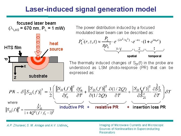
Laser-induced signal generation model focused laser beam (l. LAS = 670 nm, PL = 1 m. W) The power distribution induced by a focused modulated laser beam can be described as: heat source HTS film x-y z t temporal d spatial The thermally induced changes of S 21(f) in the probe are understood as LSM photo-response (PR) that can be expressed as: x substrate z ~ 21 21 21 where 21 inductive PR + resistive PR + insertion loss PR 21 A. P. Zhuravel, S. M. Anlage and A. V. Ustinov, Imaging of Microwave Currents and Microscopic Sources of Nonlinearities in Superconducting Resonators
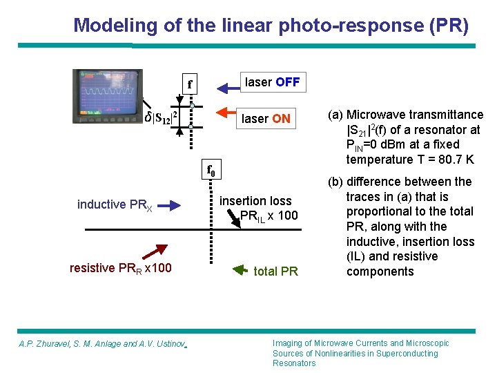
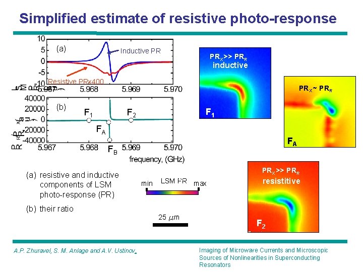
Modeling of the linear photo-response (PR) laser OFF f d|S 12|2 laser ON f 0 inductive PRX resistive PRR x 100 A. P. Zhuravel, S. M. Anlage and A. V. Ustinov, insertion loss PRIL x 100 total PR (a) Microwave transmittance |S 21|2(f) of a resonator at РIN=0 d. Bm at a fixed temperature T = 80. 7 K (b) difference between the traces in (a) that is proportional to the total PR, along with the inductive, insertion loss (IL) and resistive components Imaging of Microwave Currents and Microscopic Sources of Nonlinearities in Superconducting Resonators
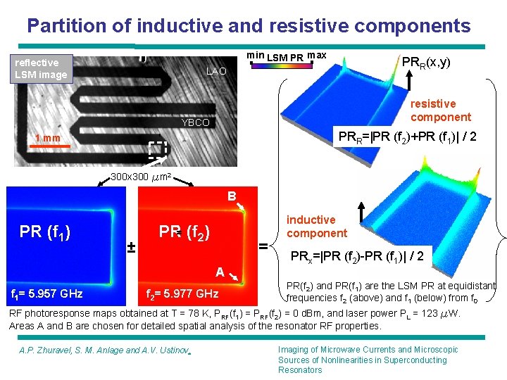
Partition of inductive and resistive components min LSM PR max reflective LSM image PRR(x, y) LAO resistive component YBCO PRR=|PR (f 2)+PR (f 1)| / 2 1 mm 300 x 300 mm 2 B PR (f 1) ± PR= (f 2) = A f 1= 5. 957 GHz f 2= 5. 977 GHz inductive component PRx=|PR (f 2)-PR (f 1)| / 2 PR(f 2) and PR(f 1) are the LSM PR at equidistant frequencies f 2 (above) and f 1 (below) from f 0 RF photoresponse maps obtained at T = 78 K, PRF(f 1) = PRF(f 2) = 0 d. Bm, and laser power PL = 123 m. W. Areas A and B are chosen for detailed spatial analysis of the resonator RF properties. A. P. Zhuravel, S. M. Anlage and A. V. Ustinov, Imaging of Microwave Currents and Microscopic Sources of Nonlinearities in Superconducting Resonators
Simplified estimate of resistive photo-response (a) Inductive PR PRX >> PRR inductive Resistive PRx 400 (b) PRX ~ PRR F 1 F 2 FA FA FB (a) resistive and inductive components of LSM photo-response (PR) (b) their ratio min PRX << PRR LSM PR max 25 mm FB A. P. Zhuravel, S. M. Anlage and A. V. Ustinov, PRX >> PRR resistitive F 2 Imaging of Microwave Currents and Microscopic Sources of Nonlinearities in Superconducting Resonators
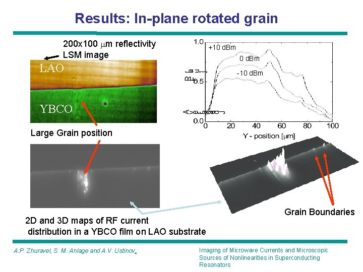
Results: In-plane rotated grain 200 x 100 mm reflectivity LSM image +10 d. Bm LAO -10 d. Bm YBCO Large Grain position 2 D and 3 D maps of RF current distribution in a YBCO film on LAO substrate A. P. Zhuravel, S. M. Anlage and A. V. Ustinov, Grain Boundaries Imaging of Microwave Currents and Microscopic Sources of Nonlinearities in Superconducting Resonators
Results: Crack reflectivity LAO YBCO JRFMAX Position of a crack y 0 JRF(x, y) x 50 mm Evident spatial modulation of rf current density along the crack formed by localized vortices pinning on a twin-domain structure of the YBCO film A. P. Zhuravel, S. M. Anlage and A. V. Ustinov, Imaging of Microwave Currents and Microscopic Sources of Nonlinearities in Superconducting Resonators
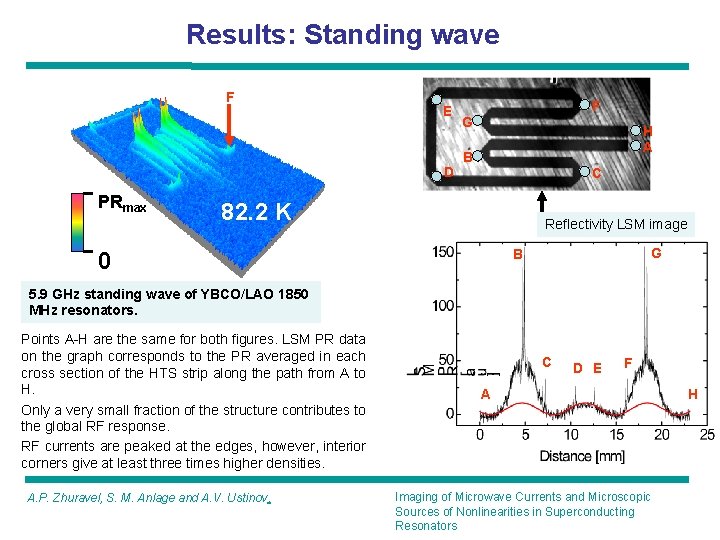
Results: Standing wave F E D PRmax F G H A B C 82. 2 K Reflectivity LSM image G B 0 5. 9 GHz standing wave of YBCO/LAO 1850 MHz resonators. Points A-H are the same for both figures. LSM PR data on the graph corresponds to the PR averaged in each cross section of the HTS strip along the path from A to H. Only a very small fraction of the structure contributes to the global RF response. RF currents are peaked at the edges, however, interior corners give at least three times higher densities. A. P. Zhuravel, S. M. Anlage and A. V. Ustinov, C D E F A Imaging of Microwave Currents and Microscopic Sources of Nonlinearities in Superconducting Resonators H
Results: Power dependence of LSM PR 10 mm PR Inductive, peak PRX(x, y) -12 d. Bm 0 d. Bm +12 d. Bm 0 25 mm Resistive, PRR(x, y) -12 d. Bm 0 d. Bm +12 d. Bm Power-dependent penetration of PRX is spatially aligned with the direction of twin-domain blocks (TDB), whereas the development of the resistive state is uncorrelated with the TDBs. Note the different spatial scale for the upper and bottom figures. A. P. Zhuravel, S. M. Anlage and A. V. Ustinov, Imaging of Microwave Currents and Microscopic Sources of Nonlinearities in Superconducting Resonators
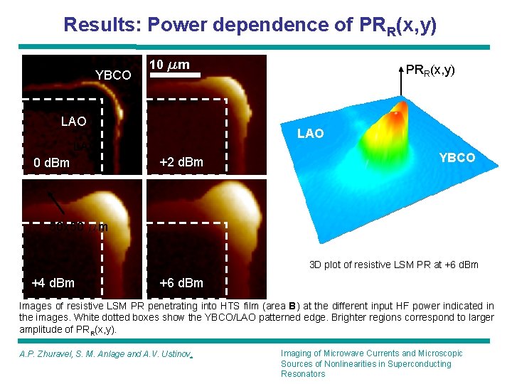
Results: Power dependence of PRR(x, y) YBCO 10 mm LAO LAO 0 d. Bm PRR(x, y) +2 d. Bm YBCO 50 x 50 mm 3 D plot of resistive LSM PR at +6 d. Bm +4 d. Bm +6 d. Bm Images of resistive LSM PR penetrating into HTS film (area B) at the different input HF power indicated in the images. White dotted boxes show the YBCO/LAO patterned edge. Brighter regions correspond to larger amplitude of PRR(x, y). A. P. Zhuravel, S. M. Anlage and A. V. Ustinov, Imaging of Microwave Currents and Microscopic Sources of Nonlinearities in Superconducting Resonators
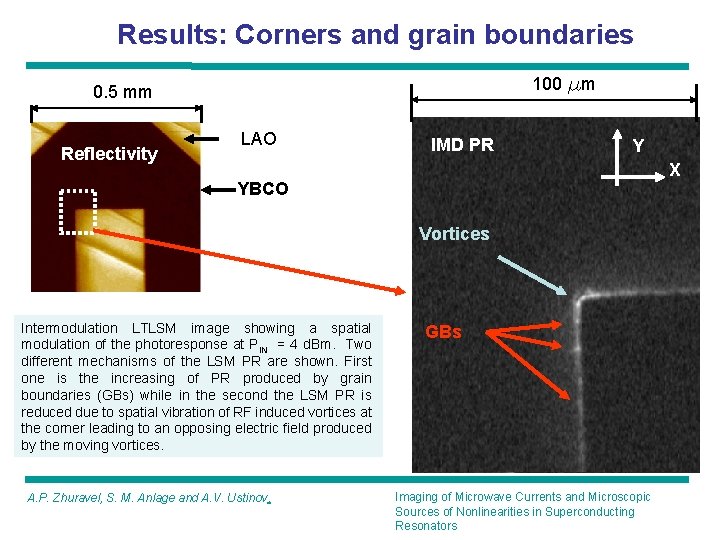
Results: Corners and grain boundaries 100 mm 0. 5 mm Reflectivity LAO IMD PR Y X YBCO Vortices ILT Intermodulation LTLSM image showing a spatial modulation of the photoresponse at PIN = 4 d. Bm. Two different mechanisms of the LSM PR are shown. First one is the increasing of PR produced by grain boundaries (GBs) while in the second the LSM PR is reduced due to spatial vibration of RF induced vortices at the corner leading to an opposing electric field produced by the moving vortices. A. P. Zhuravel, S. M. Anlage and A. V. Ustinov, GBs Imaging of Microwave Currents and Microscopic Sources of Nonlinearities in Superconducting Resonators
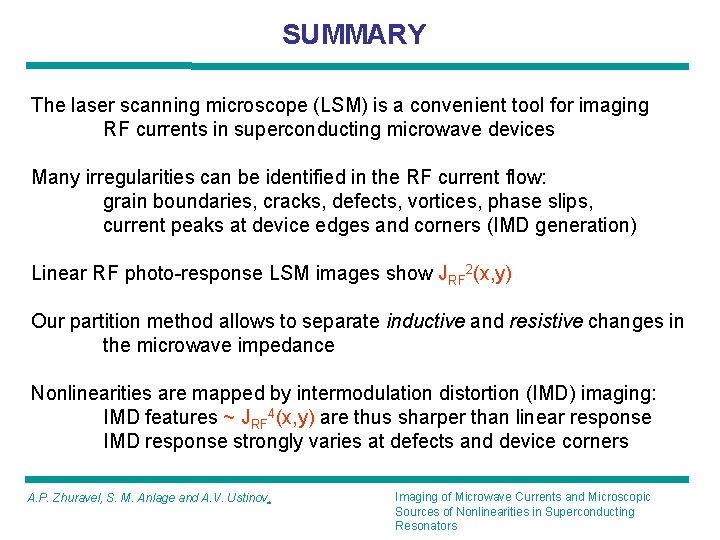
SUMMARY The laser scanning microscope (LSM) is a convenient tool for imaging RF currents in superconducting microwave devices Many irregularities can be identified in the RF current flow: grain boundaries, cracks, defects, vortices, phase slips, current peaks at device edges and corners (IMD generation) Linear RF photo-response LSM images show JRF 2(x, y) Our partition method allows to separate inductive and resistive changes in the microwave impedance Nonlinearities are mapped by intermodulation distortion (IMD) imaging: IMD features ~ JRF 4(x, y) are thus sharper than linear response IMD response strongly varies at defects and device corners A. P. Zhuravel, S. M. Anlage and A. V. Ustinov, Imaging of Microwave Currents and Microscopic Sources of Nonlinearities in Superconducting Resonators
Thanks to my collaborators Appl. Phys. Lett. 81, 4979 (2002). IEEE Trans. Appl. Superc. 13, 340 (2003). A. Low Temp. Phys. 32, 592 (2006). Appl. Phys. Lett. 88, 212503 (2006). cond-mat/0609244 (2006). We are now looking for new applications, collaborations and funding sources Steven Anlage Alexander Zhuravel