Ga Toroid Demonstrator Overview Enrico Felcini CERN 23062020

- Slides: 15
Ga. Toroid Demonstrator Overview Enrico Felcini CERN, 23/06/2020
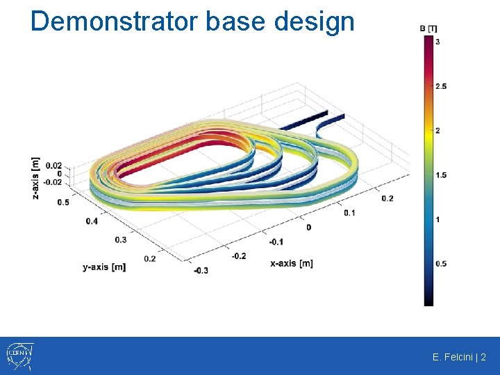
Demonstrator base design E. Felcini | 2
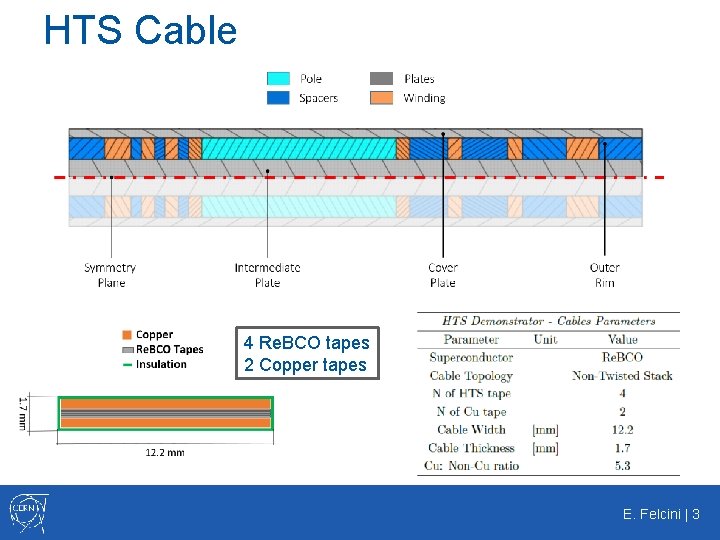
HTS Cable 4 Re. BCO tapes 2 Copper tapes E. Felcini | 3
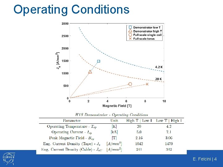
Operating Conditions E. Felcini | 4
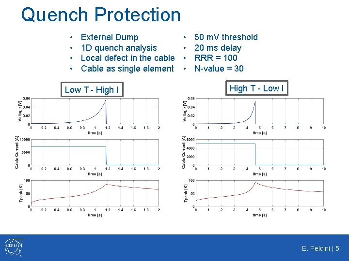
Quench Protection • • External Dump 1 D quench analysis Local defect in the cable Cable as single element Low T - High I • • 50 m. V threshold 20 ms delay RRR = 100 N-value = 30 High T - Low I E. Felcini | 5
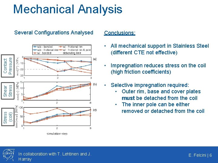
Mechanical Analysis Several Configurations Analysed Conclusions: Contact Pressure • All mechanical support in Stainless Steel (different CTE not effective) • Impregnation reduces stress on the coil (high friction coefficients) Stress (coil) Shear Stress • Selective impregnation required: • Outer rim, base and cover plates must be detached from the coil • The inner pole can be either removed or detached from the coil In collaboration with T. Lehtinen and J. Harray E. Felcini | 6
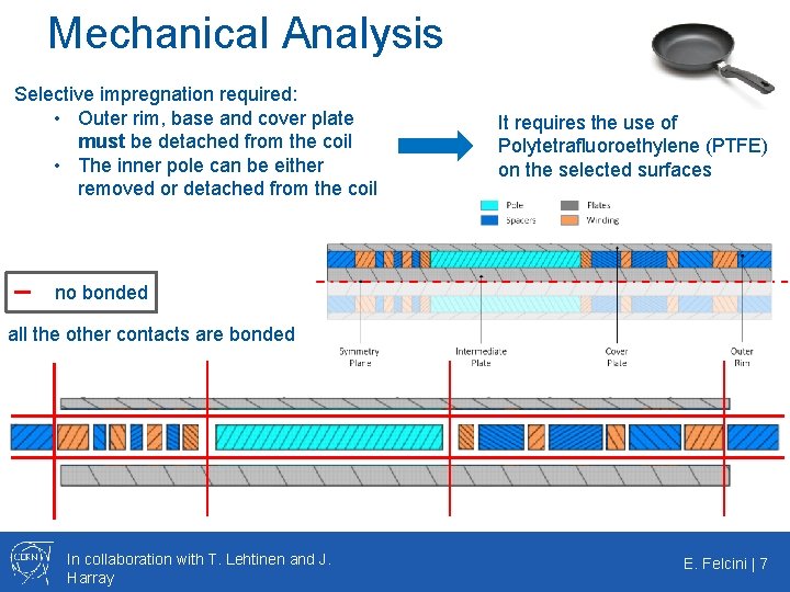
Mechanical Analysis Selective impregnation required: • Outer rim, base and cover plate must be detached from the coil • The inner pole can be either removed or detached from the coil It requires the use of Polytetrafluoroethylene (PTFE) on the selected surfaces no bonded all the other contacts are bonded In collaboration with T. Lehtinen and J. Harray E. Felcini | 7
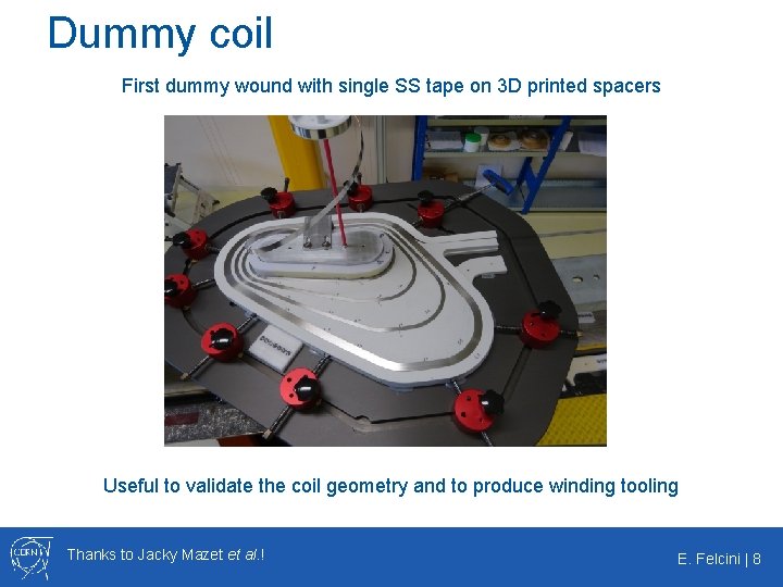
Dummy coil First dummy wound with single SS tape on 3 D printed spacers Useful to validate the coil geometry and to produce winding tooling Thanks to Jacky Mazet et al. ! E. Felcini | 8
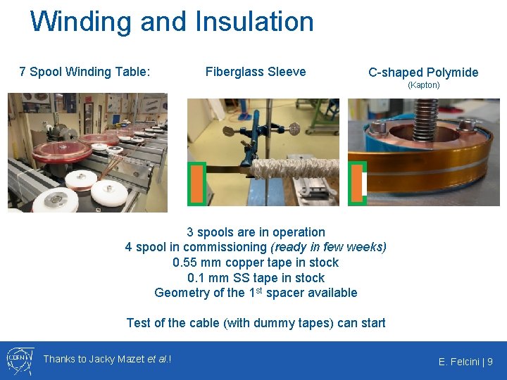
Winding and Insulation 7 Spool Winding Table: Fiberglass Sleeve C-shaped Polymide (Kapton) 3 spools are in operation 4 spool in commissioning (ready in few weeks) 0. 55 mm copper tape in stock 0. 1 mm SS tape in stock Geometry of the 1 st spacer available Test of the cable (with dummy tapes) can start Thanks to Jacky Mazet et al. ! E. Felcini | 9
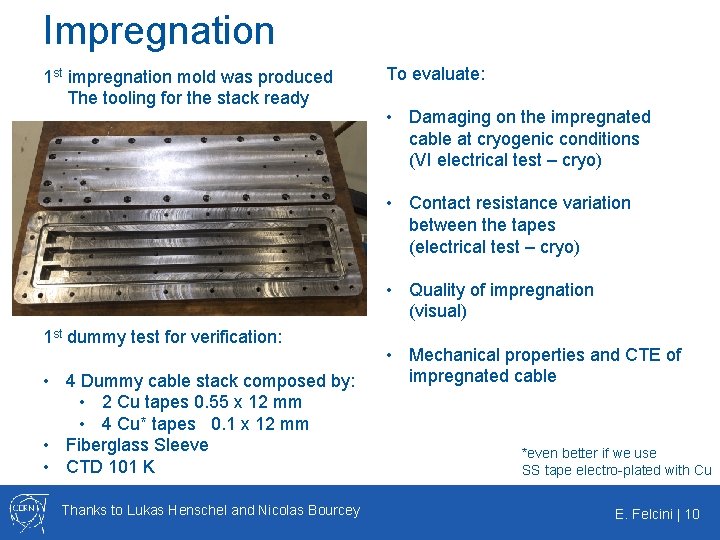
Impregnation 1 st impregnation mold was produced The tooling for the stack ready To evaluate: • Damaging on the impregnated cable at cryogenic conditions (VI electrical test – cryo) • Contact resistance variation between the tapes (electrical test – cryo) • Quality of impregnation (visual) 1 st dummy test for verification: • 4 Dummy cable stack composed by: • 2 Cu tapes 0. 55 x 12 mm • 4 Cu* tapes 0. 1 x 12 mm • Fiberglass Sleeve • CTD 101 K Thanks to Lukas Henschel and Nicolas Bourcey • Mechanical properties and CTE of impregnated cable *even better if we use SS tape electro-plated with Cu E. Felcini | 10
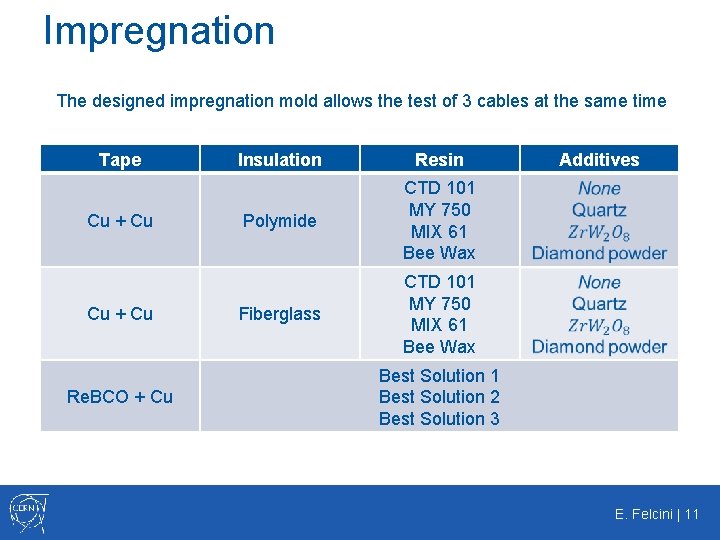
Impregnation The designed impregnation mold allows the test of 3 cables at the same time Tape Cu + Cu Re. BCO + Cu Insulation Resin Polymide CTD 101 MY 750 MIX 61 Bee Wax Fiberglass CTD 101 MY 750 MIX 61 Bee Wax Additives Best Solution 1 Best Solution 2 Best Solution 3 E. Felcini | 11
Magnetic Measurements Printed Board Circuit (PCB) • • Measure the field on specific points along the trajectory s Use of Hall probes, cross-calibrated with induction-coil sensors They are allocated in a specific PCB to precisely follow the s trajectory Similar approach to RMC Thanks to Carlo Petrone! E. Felcini | 12
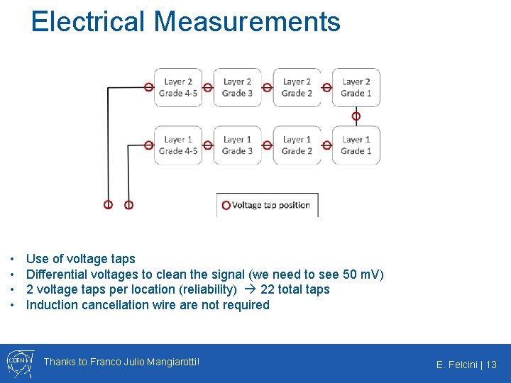
Electrical Measurements • • Use of voltage taps Differential voltages to clean the signal (we need to see 50 m. V) 2 voltage taps per location (reliability) 22 total taps Induction cancellation wire are not required Thanks to Franco Julio Mangiarotti! E. Felcini | 13
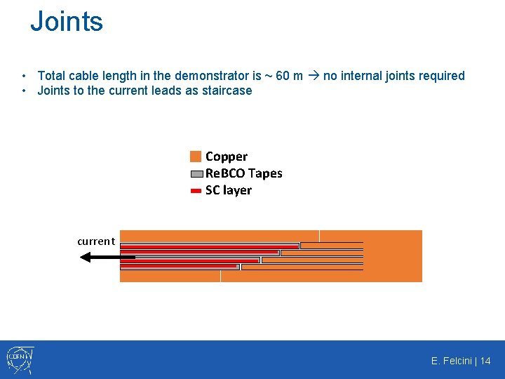
Joints • Total cable length in the demonstrator is ~ 60 m no internal joints required • Joints to the current leads as staircase Copper Re. BCO Tapes SC layer current E. Felcini | 14
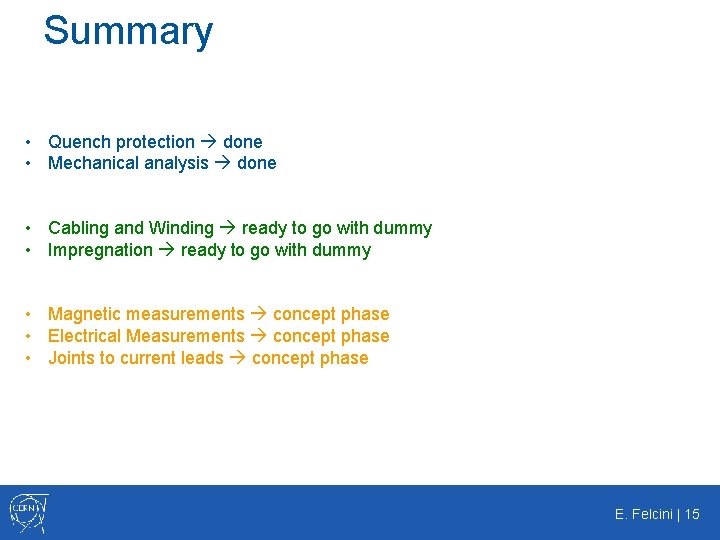
Summary • Quench protection done • Mechanical analysis done • Cabling and Winding ready to go with dummy • Impregnation ready to go with dummy • Magnetic measurements concept phase • Electrical Measurements concept phase • Joints to current leads concept phase E. Felcini | 15