Digital Design and System Implementation z Overview of

- Slides: 20
Digital Design and System Implementation z Overview of Physical Implementations z CMOS devices z CMOS transistor circuit functional behavior y Basic logic gates y Transmission gates y Tri-state buffers y Flip-flops vs. latches revisited CS 150 – Fall 2005 - Lec #26 – Digital Design – 1
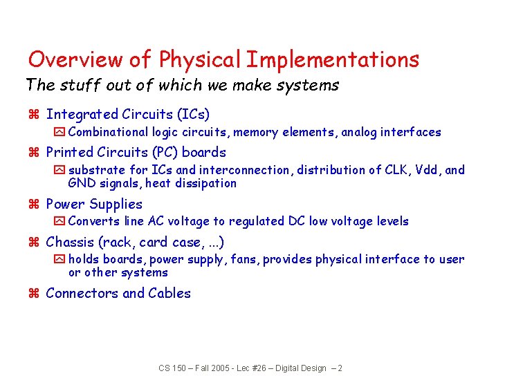
Overview of Physical Implementations The stuff out of which we make systems z Integrated Circuits (ICs) y Combinational logic circuits, memory elements, analog interfaces z Printed Circuits (PC) boards y substrate for ICs and interconnection, distribution of CLK, Vdd, and GND signals, heat dissipation z Power Supplies y Converts line AC voltage to regulated DC low voltage levels z Chassis (rack, card case, . . . ) y holds boards, power supply, fans, provides physical interface to user or other systems z Connectors and Cables CS 150 – Fall 2005 - Lec #26 – Digital Design – 2
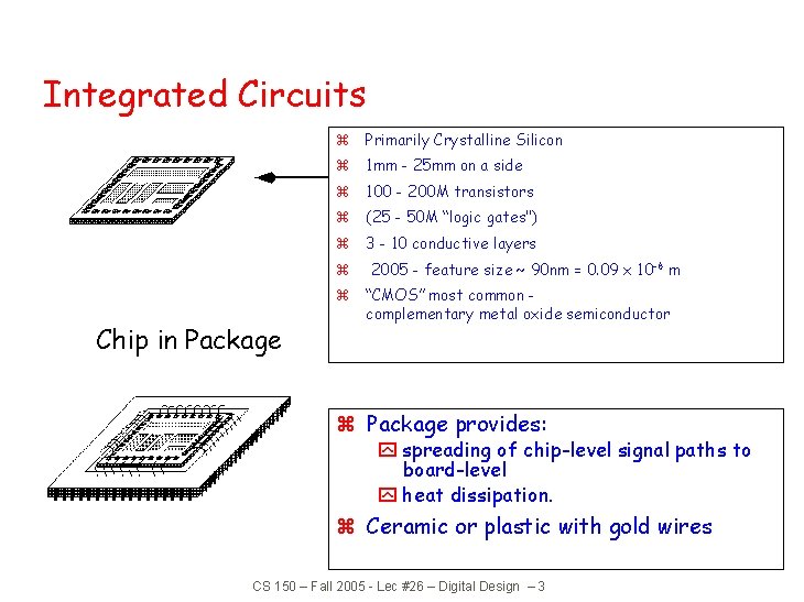
Integrated Circuits z Primarily Crystalline Silicon z 1 mm - 25 mm on a side z 100 - 200 M transistors z (25 - 50 M “logic gates") z 3 - 10 conductive layers z Chip in Package 2005 - feature size ~ 90 nm = 0. 09 x 10 -6 m z “CMOS” most common complementary metal oxide semiconductor z Package provides: y spreading of chip-level signal paths to board-level y heat dissipation. z Ceramic or plastic with gold wires CS 150 – Fall 2005 - Lec #26 – Digital Design – 3
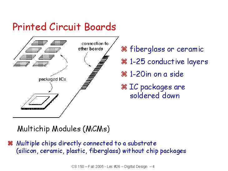
Printed Circuit Boards z fiberglass or ceramic z 1 -25 conductive layers z 1 -20 in on a side z IC packages are soldered down Multichip Modules (MCMs) z Multiple chips directly connected to a substrate (silicon, ceramic, plastic, fiberglass) without chip packages CS 150 – Fall 2005 - Lec #26 – Digital Design – 4
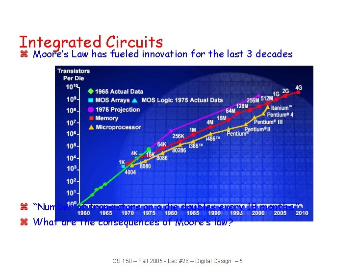
Integrated Circuits z Moore’s Law has fueled innovation for the last 3 decades z “Number of transistors on a die doubles every 18 months. ” z What are the consequences of Moore’s law? CS 150 – Fall 2005 - Lec #26 – Digital Design – 5
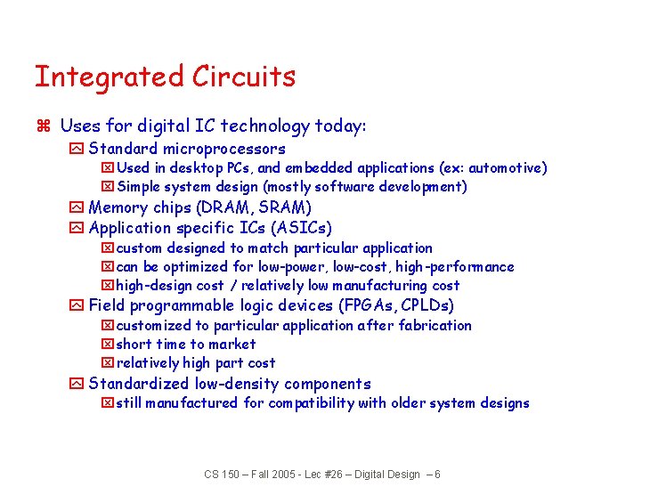
Integrated Circuits z Uses for digital IC technology today: y Standard microprocessors x Used in desktop PCs, and embedded applications (ex: automotive) x Simple system design (mostly software development) y Memory chips (DRAM, SRAM) y Application specific ICs (ASICs) x custom designed to match particular application x can be optimized for low-power, low-cost, high-performance x high-design cost / relatively low manufacturing cost y Field programmable logic devices (FPGAs, CPLDs) x customized to particular application after fabrication x short time to market x relatively high part cost y Standardized low-density components x still manufactured for compatibility with older system designs CS 150 – Fall 2005 - Lec #26 – Digital Design – 6
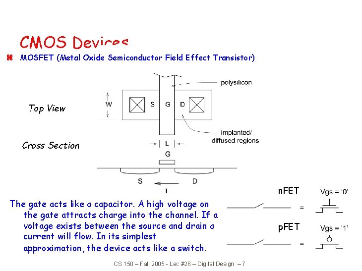
CMOS Devices z MOSFET (Metal Oxide Semiconductor Field Effect Transistor) Top View Cross Section n. FET The gate acts like a capacitor. A high voltage on the gate attracts charge into the channel. If a voltage exists between the source and drain a current will flow. In its simplest approximation, the device acts like a switch. CS 150 – Fall 2005 - Lec #26 – Digital Design – 7 p. FET
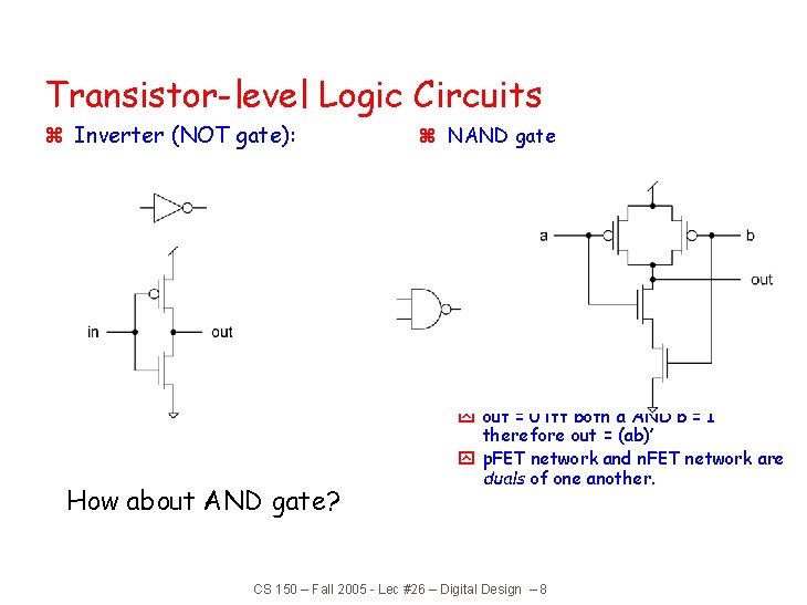
Transistor-level Logic Circuits z Inverter (NOT gate): z NAND gate z Note: How about AND gate? y out = 0 iff both a AND b = 1 therefore out = (ab)’ y p. FET network and n. FET network are duals of one another. CS 150 – Fall 2005 - Lec #26 – Digital Design – 8
Transistor-level Logic Circuits Simple rule for wiring up MOSFETs: z n. FET is used only to pass logic zero z p. Fet is used only to pass logic one z For example, NAND gate: Note: This rule is sometimes violated by expert designers under special conditions CS 150 – Fall 2005 - Lec #26 – Digital Design – 9
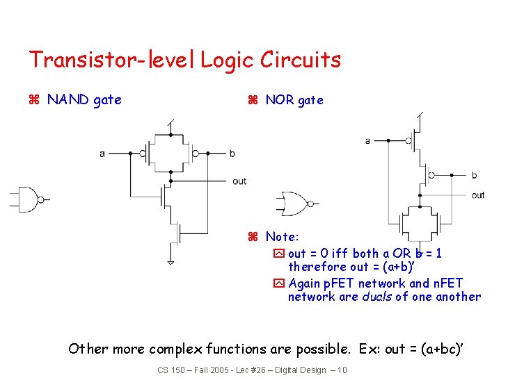
Transistor-level Logic Circuits z NAND gate z NOR gate z Note: y out = 0 iff both a OR b = 1 therefore out = (a+b)’ y Again p. FET network and n. FET network are duals of one another Other more complex functions are possible. Ex: out = (a+bc)’ CS 150 – Fall 2005 - Lec #26 – Digital Design – 10
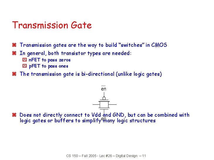
Transmission Gate z Transmission gates are the way to build “switches” in CMOS z In general, both transistor types are needed: y n. FET to pass zeros y p. FET to pass ones z The transmission gate is bi-directional (unlike logic gates) z Does not directly connect to Vdd and GND, but can be combined with logic gates or buffers to simplify many logic structures CS 150 – Fall 2005 - Lec #26 – Digital Design – 11
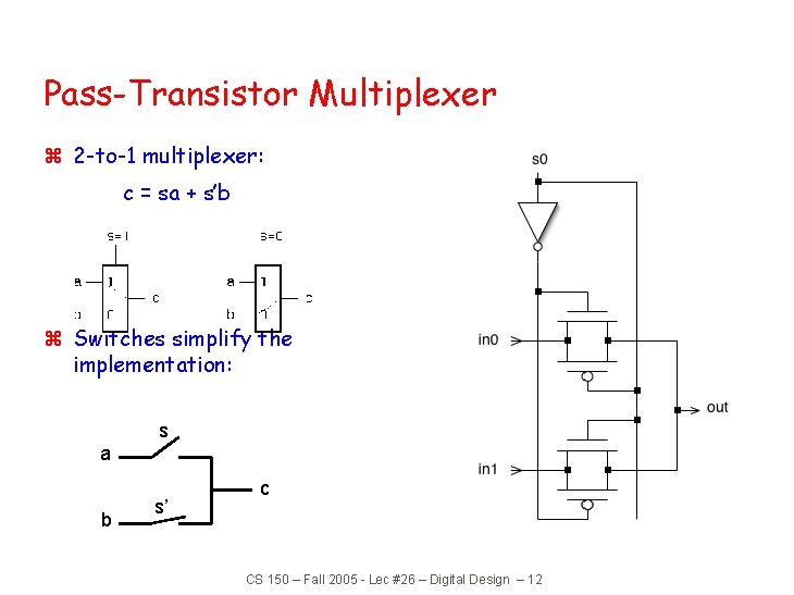
Pass-Transistor Multiplexer z 2 -to-1 multiplexer: c = sa + s’b z Switches simplify the implementation: s a b s’ c CS 150 – Fall 2005 - Lec #26 – Digital Design – 12
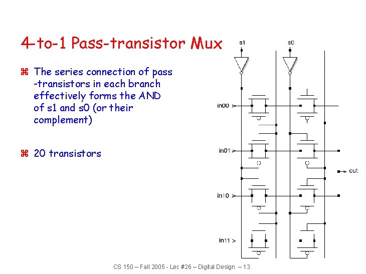
4 -to-1 Pass-transistor Mux z The series connection of pass -transistors in each branch effectively forms the AND of s 1 and s 0 (or their complement) z 20 transistors CS 150 – Fall 2005 - Lec #26 – Digital Design – 13
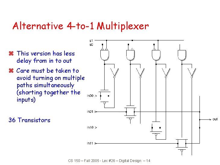
Alternative 4 -to-1 Multiplexer z This version has less delay from in to out z Care must be taken to avoid turning on multiple paths simultaneously (shorting together the inputs) 36 Transistors CS 150 – Fall 2005 - Lec #26 – Digital Design – 14
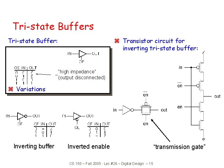
Tri-state Buffers z Transistor circuit for inverting tri-state buffer: Tri-state Buffer: “high impedance” (output disconnected) z Variations Inverting buffer Inverted enable CS 150 – Fall 2005 - Lec #26 – Digital Design – 15 “transmission gate”
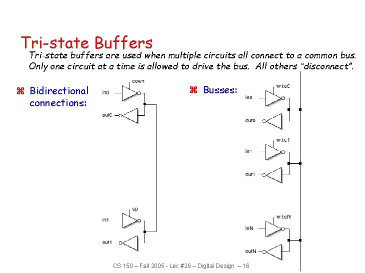
Tri-state Buffers Tri-state buffers are used when multiple circuits all connect to a common bus. Only one circuit at a time is allowed to drive the bus. All others “disconnect”. z Bidirectional connections: z Busses: CS 150 – Fall 2005 - Lec #26 – Digital Design – 16
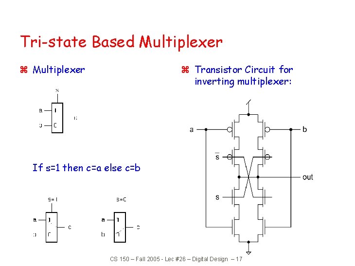
Tri-state Based Multiplexer z Transistor Circuit for inverting multiplexer: If s=1 then c=a else c=b CS 150 – Fall 2005 - Lec #26 – Digital Design – 17
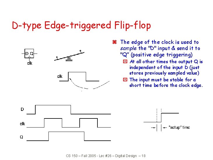
D-type Edge-triggered Flip-flop z The edge of the clock is used to sample the "D" input & send it to "Q” (positive edge triggering) y At all other times the output Q is independent of the input D (just stores previously sampled value) y The input must be stable for a short time before the clock edge. CS 150 – Fall 2005 - Lec #26 – Digital Design – 18
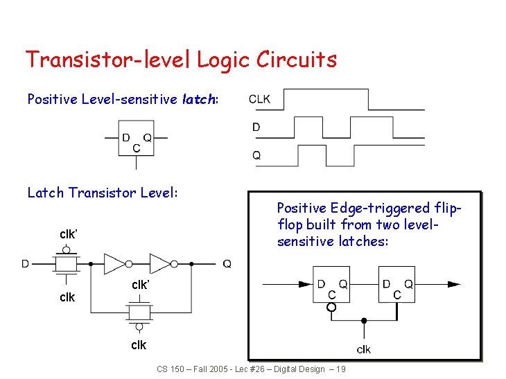
Transistor-level Logic Circuits Positive Level-sensitive latch: Latch Transistor Level: clk’ clk Positive Edge-triggered flipflop built from two levelsensitive latches: clk’ clk CS 150 – Fall 2005 - Lec #26 – Digital Design – 19
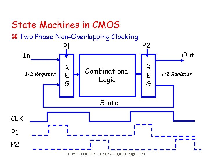
State Machines in CMOS z Two Phase Non-Overlapping Clocking P 2 P 1 In 1/2 Register R E G Combinational Logic State CLK P 1 P 2 CS 150 – Fall 2005 - Lec #26 – Digital Design – 20 R E G Out 1/2 Register