DFM Concept Proposal v 0 2 Y Leclercq


 Busy area (radiation, QXL, D 2, SCLink) On")

- Slides: 20
DFM Concept Proposal v 0. 2 Y. Leclercq, A. Kolehmainen, DFH-DFM meetings members 8 th DFH-DFM meeting : 3 Apr. 2019
DFM environment Courtesy M. Sisti C. Adorisio • Location : 45 m non IP side of SCLinks inlet shaft • Interface with : • • DSHm (cables & cryogenics volume) D 2 (cables & cryo piping) QXL (cryo piping) Integration (tunnel, Collimators, Crab Cryomodules) • Radiation : Dose ≈ 1 MGy, Neutron f. ≈ > 1. 1015 cm-2, up to 25 m. Sv/h DFHm HTS 2 x 18 k. A 2 x 13 k. A 3 x 7 k. A PT DFHx 1 PT HTS Mg. B 2 Nb. Ti Warm cable Splice Superfluid @ 1. 9 K Liquid He @ 4. 5 K Gaseous He Heater Vacuum barrier Non IP side DFM SFHe @1. 9 K Ghe <17 K UR: Service tunnel UL: Transverse tunnel IP side PT DSHm LHC tunnel Ghe @4. 5 K Splice Ghe @4. 5 K DFX Lhe @4. 5 K MBRD MBCRD D 2 CC DSHx Mg. B 2 PT PT DFHx 2 PT Ambient Dose Eq Rate 25 m. Sv/h 1 m. Sv/h PT 3 x 7 k. A 12 x 2 k. A Beam Collimators Nb. Ti PT SFHe @1. 9 K D 1 MBXF 2 x 13 k. A 8 x 0. 6 k. A
DFM concept • Concept v 0. 2 key features: • • • Same Interlink & cryo concept Inclined concept DDFX principle : Ghe mass flow created in a separated reservoir “Fountain” design to gain vertical height SCLink interface as for DFX: • Mg. B 2 -Nb. Ti splices protected in perforated cylinder • Only Nb. Ti leads accessible • Basic concept 1. 2. 3. 4. Lhe injection in splice volume Level flows in side reservoir by gravity Heater vaporises liquid (based on DFHm needs) Level gauge control LHE inlet to ensure level Plug LHe Inlet
Nominal configuration Electrical: • Mg. B 2 -Nb. Ti Splices protected • Nb. Ti-Nb. Ti splices on either side of plug Fill reservoir Cryogenics: 14 litres 100 700 Mg. B 2 -Nb. Ti Splices +50 mm Nominal level Inlet reservoir 10 min @ 2 g. s-1 100 -50 mm 10 litres Heaters volume Superfluid in interlink Splices immersed in LHE Fountain principle 10 min buffer at nominal conditions Insulation vacuum ← SCLink to DFHm 100 • Vacuum barrier in DFM • Vacuum barrier at plug level IFS Fill reservoir 8 litres Ø Mg. B 250 x 6 00 2 -Nb Ti sp lices Interlink To D 2 Plug 16 min @ 20 W Top splices • • LHe inlet 20°
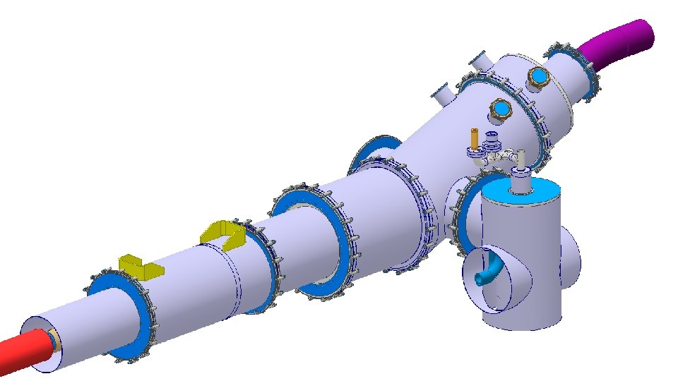
Interfaces Vacuum flange SCLink configuration for transport • SCLink: • • As for DFX Independent inner and outer flexibles Mg. B 2 -Nb. Ti protected Insulation vacuum on DFM side • Cryogenics: • Jumper on reservoir side • 1 x LHE In + 1 x GHE out + 1 x TSInterlink + 2 x 4 -6 Heat Ex. • Location : close to today’s jumper proposal (work on going) EDMS 1750118 Weldable He flange Nb. Ti leads Ø 250 x 600 Mg. B 2 -Nb. Ti splices Protected sleeve
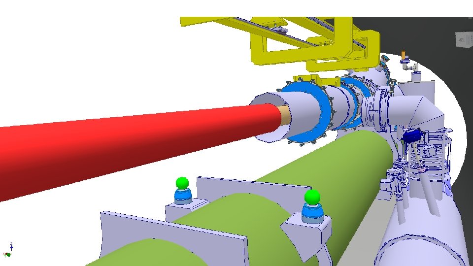
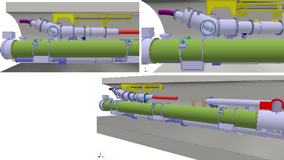
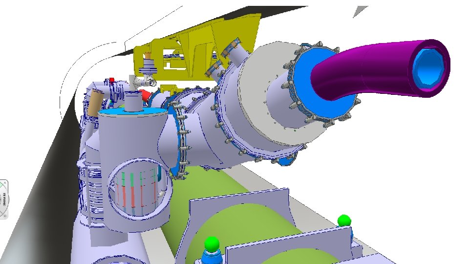
Integration on going work QXL • DFM located above D 2 • Distant enough to allow independent assemblies SCLink • Longitudinal position in discussion • Not relevant for concept within ≈1 -2 m DFM • Cryo interface: • 1 dedicated jumper (Details TBD) D 2 • SCLink interface: QXL • As for DFX concept • Interlink interface: • Plug at DFM level (interlink work on going) • Maintenance: DFM • Pumps, safety devices, V-taps and instru accessible • Cryo maintenance access TBD • Integration proposal: (TBD) SCLink • Roof support • Independent assembly D 2 -DFM • Compatible with QXL maintenance ? Interlink D 2 QXL Interlink
Assembly preliminary sequence Plug Nb. Ti-Nb. Ti splices 1. Initial conditions: • D 2 present • Interlink installed until plug Nb. Ti leads 2. DFM installed rotated of 10 deg 3. SCLink insertion with limited angle 4. 5. 6. 7. DFM rotation to nominal Weld jumper interfaces Nb. Ti-Nb. Ti splices He and Vacuum vessels closure Weld He volumes Nb. Ti-Nb. Ti splices Interlink
Next Steps • Interlink integration and access for maintenance to QXL • Interface with Cryolines • Interface with integration / tunnel / D 2 • Assembly sequence detailed • IFS design
Spare slides
SCLink He jacket welding to DFM helium vessel
SCLink Nb. Ti leads soldering to Plug Nb. Ti leads
Nominal configuration
View from tunnel
DDFX cryo layout TT 839 TT 838 EH 834 165 - 80% : limit for gas lines - 58% : Nominal 40 - 42% - 25% - 13% - 0% 97 - 80% TT 832 TT 833 EH 831 EH 835 LT 832 40 44 TT 834 65 30 TT 831 134 LT 831 EH 831 - 42% : TT 831 - 25% : Middle plane / max Ø - 13% : start filling heater volume - 0% : min level reading
DFM environment (not today’s key topic) Busy area (radiation, QXL, D 2, SCLink) On going discussions to study feasibility Sequence: • DFM concept • DFM integration • Iterations WP 15 137340 mm D 2 CC 1 CC 2 Updated D 2 total length increased 300 mm 152383 mm Avoid interferences DFM Space reservation D 2 Motorised jacks added Area under study Define connection to jumper Valves between the 2 jumpers Define Interlink routing SM fixed DFM Space reservation Courtesy M. Gonzalez de la Aleja around 5 m Provide access to the valves SM fixed
DFM concept • 4 th DFH-DFM meeting actions: • Reduce distance between outer and inner SCLink flanges • Study supporting options