Crystallography and Structure Overview n Crystal Structure matter


.")


 • Rare due to low packing density (only Po –")
 Volume of atoms in unit cell* APF = Volume of")
 • Atoms touch each other along cube diagonals within")

 • Atoms touch each other along face diagonals. --Note:")

 ex: Cd, Mg, Ti, Zn • ABAB. . . Stacking")
- Slides: 16
Crystallography and Structure
Overview: n Crystal Structure – matter assumes a periodic shape ¨ Non-Crystalline or Amorphous “structures” exhibit no long range periodic shapes ¨ Xtal Systems – not structures but potentials ¨ FCC, BCC and HCP – common Xtal Structures for metals Point, Direction and Planer ID’ing in Xtals n X-Ray Diffraction and Xtal Structure n
CRYSTAL STRUCTURES Crystal Structure Means: PERIODIC ARRANGEMENT OF ATOMS/IONS OVER LARGE ATOMIC DISTANCES àLeads to structure displaying LONG-RANGE ORDER that is Measurable and Quantifiable All metals, many ceramics, and some polymers exhibit this “High Bond Energy” and a More Closely Packed Structure
Materials Lacking Long range order Amorphous Materials These less densely packed lower bond energy “structures” can be found in Metals are observed in Ceramic GLASS and many “plastics”
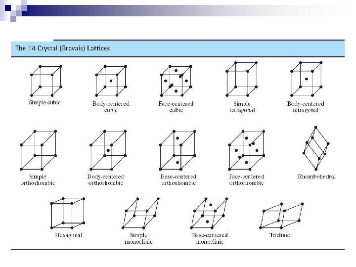
Crystal Systems – Some Definitional information Unit cell: smallest repetitive volume which contains the complete lattice pattern of a crystal. 7 crystal systems of varying symmetry are known These systems are built by changing the lattice parameters: a, b, and c are the edge lengths , , and are interaxial angles Fig. 3. 4, Callister 7 e.
Crystal Systems Crystal structures are divided into groups according to unit cell geometry (symmetry).
Metallic Crystal Structures • Tend to be densely packed. • Reasons for dense packing: - Typically, only one element is present, so all atomic radii are the same. - Metallic bonding is not directional. - Nearest neighbor distances tend to be small in order to lower bond energy. - Electron cloud shields cores from each other • Have the simplest crystal structures. We will examine three such structures (those of engineering importance) called: FCC, BCC and HCP – with a nod to Simple Cubic
Crystal Structure of Metals – of engineering interest
Simple Cubic Structure (SC) • Rare due to low packing density (only Po – Polonium -has this structure) • Close-packed directions are cube edges. • Coordination No. = 6 (# nearest neighbors) for each atom as seen (Courtesy P. M. Anderson)
Atomic Packing Factor (APF) Volume of atoms in unit cell* APF = Volume of unit cell *assume hard spheres • APF for a simple cubic structure = 0. 52 atoms unit cell a R=0. 5 a close-packed directions contains (8 x 1/8) = 1 atom/unit cell Adapted from Fig. 3. 23, Callister 7 e. APF = volume atom 4 p (0. 5 a) 3 1 3 a 3 volume unit cell Here: a = Rat*2 Where Rat is the ‘handbook’ atomic radius
Body Centered Cubic Structure (BCC) • Atoms touch each other along cube diagonals within a unit cell. --Note: All atoms are identical; the center atom is shaded differently only for ease of viewing. ex: Cr, W, Fe ( ), Tantalum, Molybdenum • Coordination # = 8 (Courtesy P. M. Anderson) Adapted from Fig. 3. 2, Callister 7 e. 2 atoms/unit cell: (1 center) + (8 corners x 1/8)
Atomic Packing Factor: BCC 3 a a 2 a R a Close-packed directions: length = 4 R = 3 a atoms volume 4 3 p ( 3 a/4) 2 unit cell atom 3 APF = volume Adapted from 3 a Fig. 3. 2(a), Callister 7 e. unit cell • APF for a body-centered cubic structure = 0. 68
Face Centered Cubic Structure (FCC) • Atoms touch each other along face diagonals. --Note: All atoms are identical; the face-centered atoms are shaded differently only for ease of viewing. ex: Al, Cu, Au, Pb, Ni, Pt, Ag • Coordination # = 12 Adapted from Fig. 3. 1, Callister 7 e. 4 atoms/unit cell: (6 face x ½) + (8 corners x 1/8) (Courtesy P. M. Anderson)
Atomic Packing Factor: FCC • APF for a face-centered cubic structure = 0. 74 The maximum achievable APF! 2 a a Adapted from Fig. 3. 1(a), Callister 7 e. Close-packed directions: length = 4 R = 2 a (a = 2 2*R) Unit cell contains: 6 x 1/2 + 8 x 1/8 = 4 atoms/unit cell atoms volume 4 3 p ( 2 a/4) 4 unit cell atom 3 APF = volume 3 a unit cell
Hexagonal Close-Packed Structure (HCP) ex: Cd, Mg, Ti, Zn • ABAB. . . Stacking Sequence • 3 D Projection • 2 D Projection A sites c Top layer B sites Middle layer A sites a Bottom layer Adapted from Fig. 3. 3(a), Callister 7 e. • Coordination # = 12 6 atoms/unit cell • APF = 0. 74 • c/a = 1. 633 (ideal)