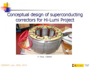
Conceptual design of superconducting correctors for HiLumi Project


- Slides: 16

Conceptual design of superconducting correctors for Hi-Lumi Project (v 2) F. Toral - CIEMAT, March 7 th, 2013

Outline • • Last magnetic calculations Cross section of the magnets Superferric dipole design Conclusions 2

Last magnetic calculations • New calculations have been done assuming a higher nonlinearity of the transfer function: 20% of saturation at nominal current. That is, the actual field at nominal current is 80% of the computed value by extrapolation of the transfer function at low currents. • The requirement on integrated strength of the decapole and dodecapole, normal and skew in both cases, has been reduced by 25%. • The cross talk between two identical consecutive magnets is negligible. Next model will include different magnets, to define the minimum distance between them. 3

Last magnetic calculations Total length (m) 2, 958 WP 2 requirements Roxie simulation Superferric option Int Strenght at 50 Int Pole field 2 mm strength Mech length Strength D Order Aperture Saturation Coil length Coil straight length Block current (m) (A) Number of turns Int Strenght required/ at 50 mm given Current Wire bare diameter L (A) (mm) (H) (mm) (T/m^(n -2)) (m) (T/m^(n -1)) (T) (adim) (T m) MCQSX Skew 2 150 1, 014 0, 914 1, 75 1, 04 0, 896 0, 864 53000 346 153, 2 0, 7 1, 99 1, 00 1, 01 MCSX Normal 3 150 0, 060 0, 136 1, 25 1, 04 0, 116 0, 092 24000 228 105, 3 0, 5 0, 167 0, 06 1, 00 MCSSX Skew 3 150 0, 060 0, 136 1, 25 1, 04 0, 116 0, 092 24000 228 105, 3 0, 5 0, 167 0, 06 1, 00 MCOX MCOSX MCDX Normal Skew Normal 4 4 5 150 150 0, 040 0, 140 0, 170 1, 25 1, 40 1, 02 1, 05 0, 120 0, 150 0, 096 0, 126 17400 165 165 105, 5 0, 093 0, 138 0, 04 1, 00 MCDSX Skew 5 150 0, 040 0, 170 1, 40 1, 05 0, 150 0, 126 17400 165 105, 5 0, 138 0, 02 2, 00 MCTX Normal 6 150 0, 119 0, 608 1, 65 1, 05 0, 588 0, 564 16600 165 100, 6 0, 5 0, 6 0, 12 1, 00 MCTSX Skew 6 150 0, 020 0, 144 1, 40 1, 04 0, 124 0, 100 14000 165 84, 8 0, 5 0, 111 0, 02 1, 02 Total length (m) 2, 416 Roxie simulation Order Aperture (adim) (mm) MCQSX Skew 2 150 0, 997 0, 746 2, 20 MCSX Normal 3 150 0, 060 0, 136 MCSSX 3 150 0, 060 0, 136 MCOX Normal 4 150 0, 040 0, 140 MCOSX 4 150 0, 040 MCDX Normal 5 150 0, 031 MCDSX 5 150 MCTX Normal 6 MCTSX 6 Skew Superferric option Saturation Coil length Coil straight length Block current (adim) (m) (A) (T m) 0, 81 0, 726 0, 694 76000 738 103, 0 0, 7 5, 86 1, 00 1, 25 0, 96 0, 116 0, 092 24000 228 105, 3 0, 5 0, 167 0, 06 1, 00 1, 25 0, 98 0, 120 0, 096 17400 165 105, 5 0, 093 0, 04 1, 00 0, 140 1, 25 0, 98 0, 120 0, 096 17400 165 105, 5 0, 093 0, 04 1, 00 0, 116 2, 00 0, 80 0, 096 0, 072 25000 198 126, 3 0, 5 0, 131 0, 03 1, 03 0, 031 0, 116 2, 00 0, 80 0, 096 0, 072 25000 198 126, 3 0, 5 0, 131 0, 02 2, 06 150 0, 092 0, 382 2, 10 0, 80 0, 362 0, 338 25000 185 135, 1 0, 5 0, 403 0, 09 1, 02 150 0, 016 0, 104 2, 10 0, 81 0, 084 0, 060 20000 185 108, 1 0, 5 0, 093 0, 015 1, 08 Int Strenght at 50 Int Pole field 2 mm strength Mech length Strength D (T/m^(n(T m) 2)) (m) 1)) (T) Number of turns Current Wire bare diameter L (A) (mm) (H) WP 2 requirements Int Strenght required/ at 50 mm given 4

Outline • • Last magnetic calculations Cross section of the magnets Superferric dipole design Conclusions 5

Cross section: quadrupole 6

Transfer function: quadrupole Units (1 E-4) Gradient T/m Normalized current 7

Cross section: sextupole 8

Cross section: octupole 9

Cross section: decapole 10

Cross section: dodecapole 11

Cross section: dodecapole 12

Outline • • Last magnetic calculations Cross section of the magnets Superferric dipole design Conclusions 13

Superferric dipole design (I) 14

Superferric dipole design (II) n n n The maximum allowed outer diameter is 620 mm. The present design has not included iron holes: there are holes for the cryogenic lines, but others can be used for the field shaping due to the iron saturation. The present optimization has been done only by iron pole morphing. The main field is about 1. 5 T, which is too low to be competitive with a cos-theta design. What is the request for the field quality? 10 units (1 E-3) is good enough? Optimization is still ongoing. 15

Conclusions n n n A new design with higher saturation has been performed (20% of non-linearity of the transfer function). The cross talk between consecutive magnets is being computed. The cross section of the different magnets have been shown. A superferric dipole design is being analysed to provide 2. 5 or 4 Tm. The optimization is still ongoing. The framework for this Collaboration needs to be defined. 16
 Superconducting tunnel junction
 Superconducting tunnel junction
 Coband
 Superconducting tunnel junction
 Superconducting electronics
 Western superconducting
 Youtube.com
 Transition edge sensor
 Meissner effect equation
 Superconducting devices in quantum optics
 Oxford superconducting technology
 Conceptual design database
 Kontinuitetshantering i praktiken
 Typiska novell drag
 Nationell inriktning för artificiell intelligens
 Returpilarna
 Varför kallas perioden 1918-1939 för mellankrigstiden?
