Automatic Test Equipment Development with CON Seo Dong




- Slides: 15
Automatic Test Equipment Development with C-ON Seo Dong Gon Yonsei University
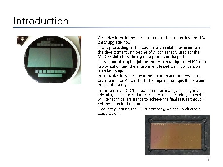
Introduction We strive to build the infrastructure for the sensor test for ITS 4 chips upgrade now. It was proceeding on the basis of accumulated experience in the development and testing of silicon sensors used for the MPC-EX detectors, through the process in the past. I have been doing the job for the system design for ALICE chip probe station and the environment tested on silicon sensors from last August. In particular, let's talk about the situation and progress in the preparation for Automatic Test Equipment designs that we aim in our laboratory. In this process, C-ON corporation’s technology, has significant advantages in automation machinery manufacturing, in need will be technical assistance to achieve the final results through collaboration in the future. Frequently, visiting the C-ON Company, we has conducted a consultation. 2
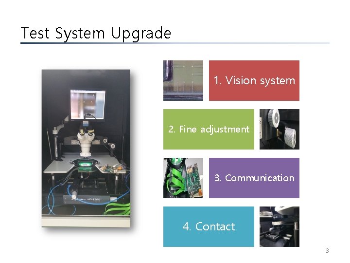
Test System Upgrade 1. Vision system 2. Fine adjustment 3. Communication 4. Contact 3
System configuration 1. Warpage of chips 2. Tilt for chuck 4
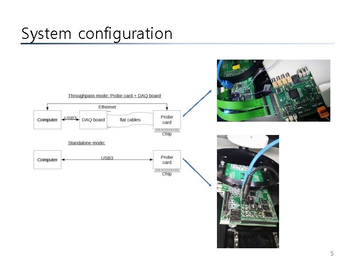
System configuration 5
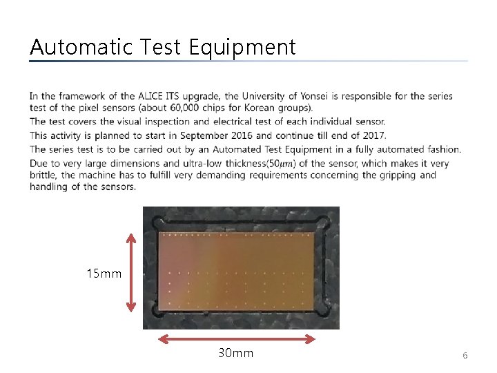
Automatic Test Equipment • 15 mm 30 mm 6
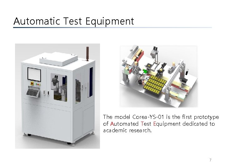
Automatic Test Equipment The model Corea-YS-01 is the first prototype of Automated Test Equipment dedicated to academic research. 7
Automatic Test Equipment 8
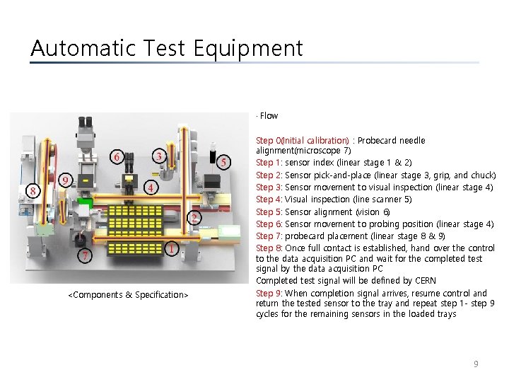
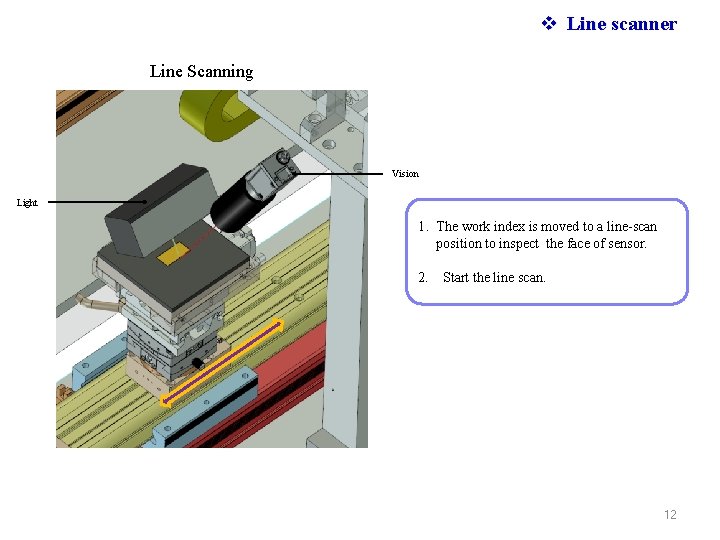
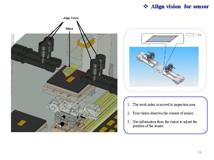
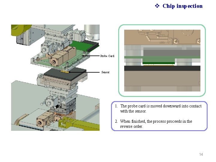
Automatic Test Equipment · Flow <Components & Specification> Step 0(Initial calibration) : Probecard needle alignment(microscope 7) Step 1: sensor index (linear stage 1 & 2) Step 2: Sensor pick-and-place (linear stage 3, grip, and chuck) Step 3: Sensor movement to visual inspection (linear stage 4) Step 4: Visual inspection (line scanner 5) Step 5: Sensor alignment (vision 6) Step 6: Sensor movement to probing position (linear stage 4) Step 7: probecard placement (linear stage 8 & 9) Step 8: Once full contact is established, hand over the control to the data acquisition PC and wait for the completed test signal by the data acquisition PC Completed test signal will be defined by CERN Step 9: When completion signal arrives, resume control and return the tested sensor to the tray and repeat step 1 - step 9 cycles for the remaining sensors in the loaded trays 9
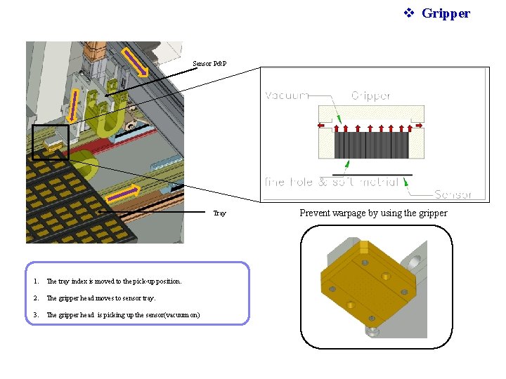
v Gripper Sensor P&P Tray 1. The tray index is moved to the pick-up position. 2. The gripper head moves to sensor tray. 3. The gripper head is picking up the sensor(vacuum on) Prevent warpage by using the gripper
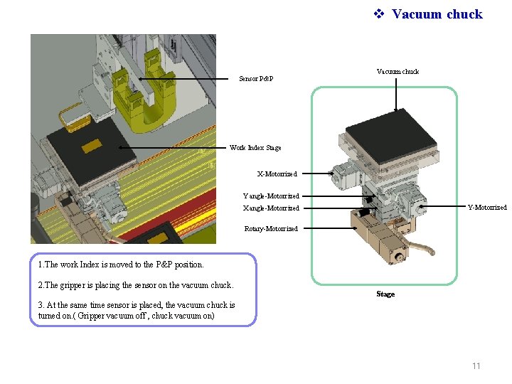
v Vacuum chuck Sensor P&P Vacuum chuck Work Index Stage X-Motorrized Y angle-Motorrized Y-Motorrized X angle-Motorrized Rotary-Motorrized 1. The work Index is moved to the P&P position. 2. The gripper is placing the sensor on the vacuum chuck. Stage 3. At the same time sensor is placed, the vacuum chuck is turned on. ( Gripper vacuum off , chuck vacuum on) 11
v Line scanner Line Scanning Vision Light 1. The work index is moved to a line-scan position to inspect the face of sensor. 2. Start the line scan. 12
v Align vision for sensor Align Vision Mirror 1. The work index is moved to inspection area. 2. Four vision observes the corners of sensor. 3. Use information from the vision to adjust the position of the sensor. 13
v Chip inspection Probe Card Sensor 1. The probe card is moved downward into contact with the sensor. 2. When finished, the process proceeds in the reverse order. 14
Conclusions C-ON is ready to fabricate the ATE COREA-YS-01 after 8 months of operation once order is made. The ATE, which will be a property of the ALICE Collaboration, will be installed and operated at the Yonsei University for the period needed to complete the series test (2016 -2018) 1) Continuous communication with C-ON 2) Liaison for ATE