An Open Educational Resource on Manufacturing Processes Lesson


- Slides: 33
An Open Educational Resource on Manufacturing Processes Lesson 4 Metal Cutting Processes By, Dattatray A. Chopade Tejas D. Bhirud Sachin L. Nimbulkar G. H. Raisoni Institute of Engineering and Management, Jalgaon To view a copy of this license, visit http: //creativecommons. org/licenses/by-sa/4. 0/
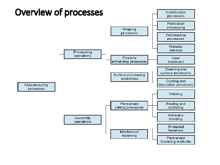
Overview of processes
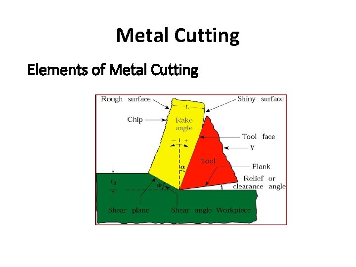
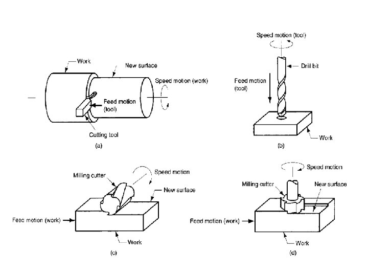
Metal Cutting Elements of Metal Cutting
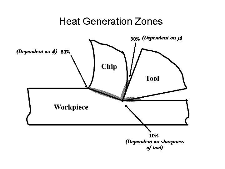
Heat Generation Zones 30% (Dependent on m) (Dependent on f) 60% 10% (Dependent on sharpness of tool)
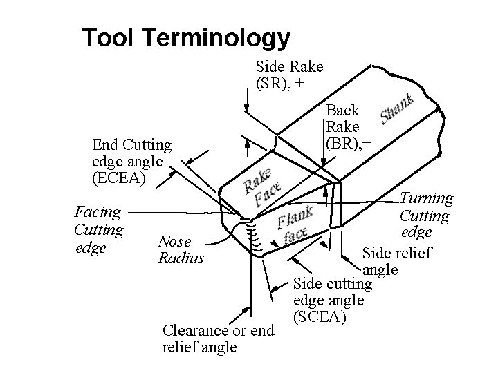
Tool Terminology Side Rake (SR), + End Cutting edge angle (ECEA) Facing Cutting edge Nose Radius Clearance or end relief angle Back Rake (BR), + Turning Cutting edge Side relief angle Side cutting edge angle (SCEA)
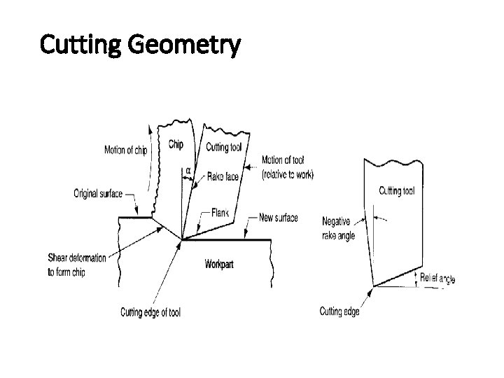
Cutting Geometry
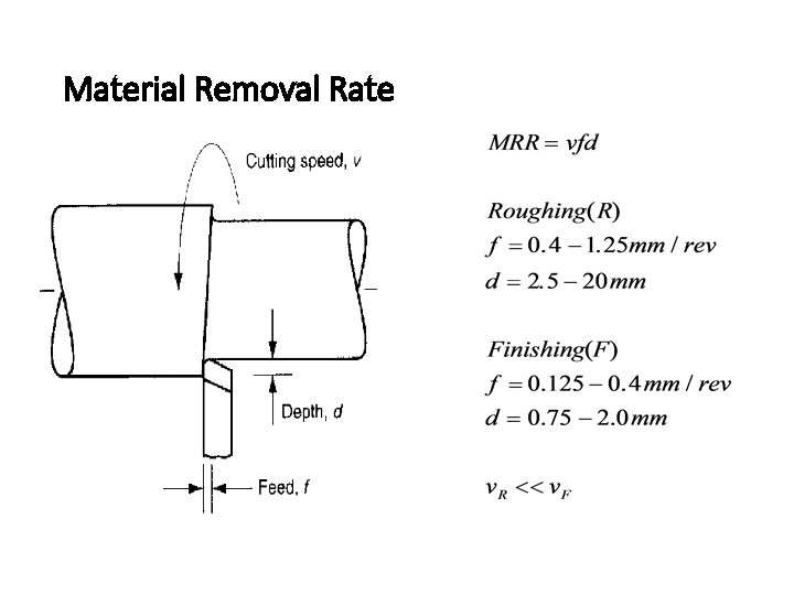
Material Removal Rate
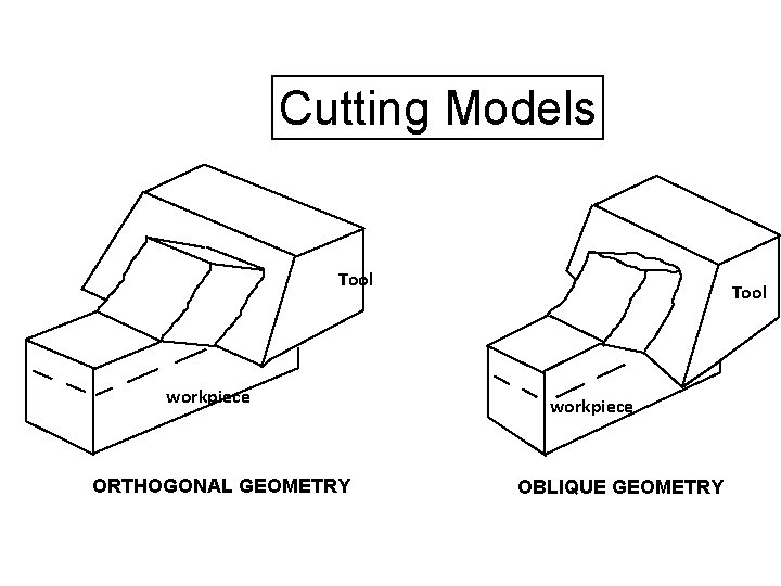
Cutting Models Tool workpiece ORTHOGONAL GEOMETRY Tool workpiece OBLIQUE GEOMETRY
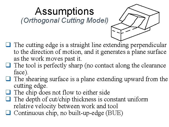
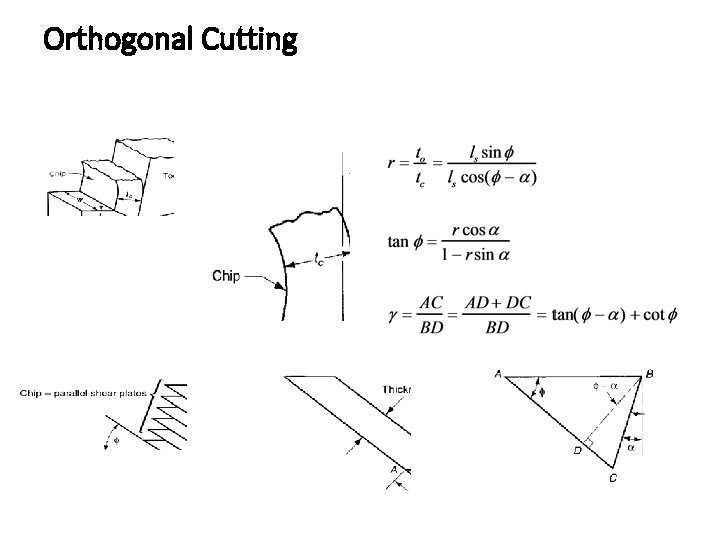
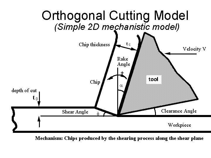
Assumptions (Orthogonal Cutting Model) q The cutting edge is a straight line extending perpendicular to the direction of motion, and it generates a plane surface as the work moves past it. q The tool is perfectly sharp (no contact along the clearance face). q The shearing surface is a plane extending upward from the cutting edge. q The chip does not flow to either side q The depth of cut/chip thickness is constant uniform relative velocity between work and tool q Continuous chip, no built-up-edge (BUE)
Orthogonal Cutting
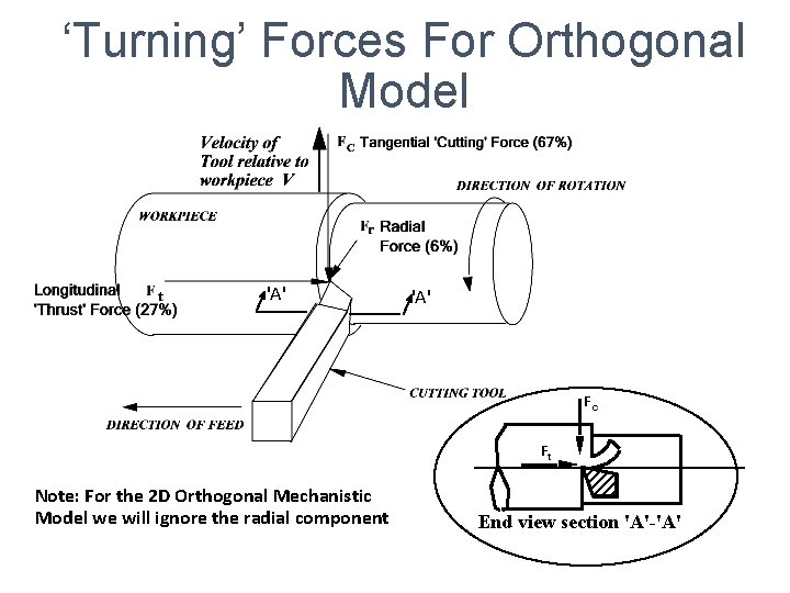
‘Turning’ Forces For Orthogonal Model 'A' Fc Ft Note: For the 2 D Orthogonal Mechanistic Model we will ignore the radial component End view section 'A'-'A'
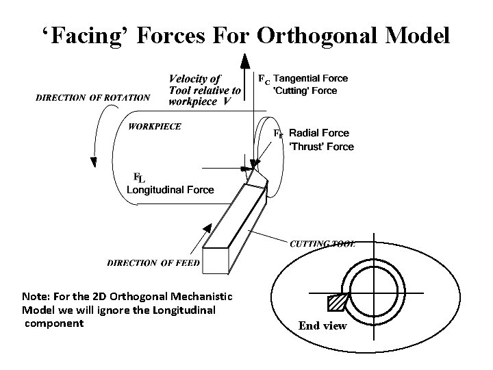
‘Facing’ Forces For Orthogonal Model Note: For the 2 D Orthogonal Mechanistic Model we will ignore the Longitudinal component End view
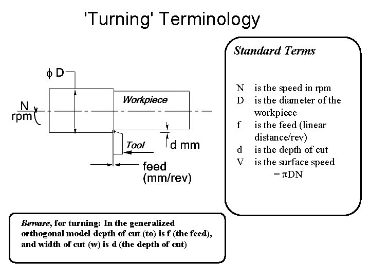
'Turning' Terminology Standard Terms N is the speed in rpm D is the diameter of the workpiece f is the feed (linear distance/rev) d is the depth of cut V is the surface speed = p. DN Beware, for turning: In the generalized orthogonal model depth of cut (to) is f (the feed), and width of cut (w) is d (the depth of cut)
Orthogonal Cutting Model (Simple 2 D mechanistic model) tc Chip thickness Velocity V Rake Angle + Chip depth of cut a tool Tool t 0 Shear Angle f Clearance Angle Workpiece Mechanism: Chips produced by the shearing process along the shear plane
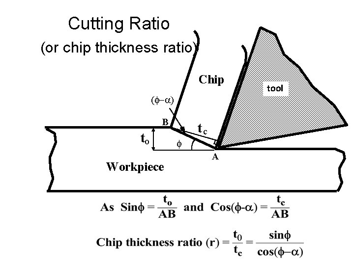
Cutting Ratio (or chip thickness ratio) Chip (f-a) B to Workpiece tc f A tool
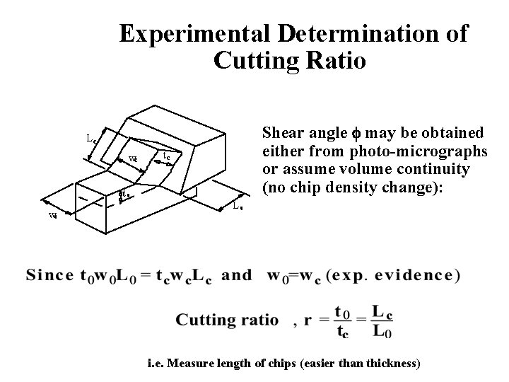
Experimental Determination of Cutting Ratio Shear angle f may be obtained either from photo-micrographs or assume volume continuity (no chip density change): Lc wc tc t 0 w 0 L 0 i. e. Measure length of chips (easier than thickness)
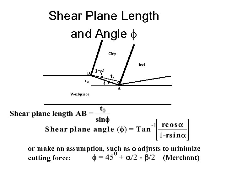
Shear Plane Length and Angle f Chip tool B to (f-a) tc f A Workpiece or make an assumption, such as f adjusts to minimize (Merchant) cutting force:
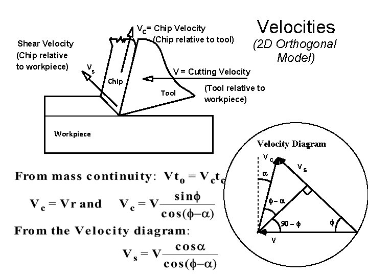
Shear Velocity (Chip relative to workpiece) Vc = Chip Velocity (Chip relative to tool) V s Chip Velocities (2 D Orthogonal Model) V = Cutting Velocity Tool (Tool relative to workpiece) Workpiece Velocity Diagram Vc Vs a f-a 90 - f V f
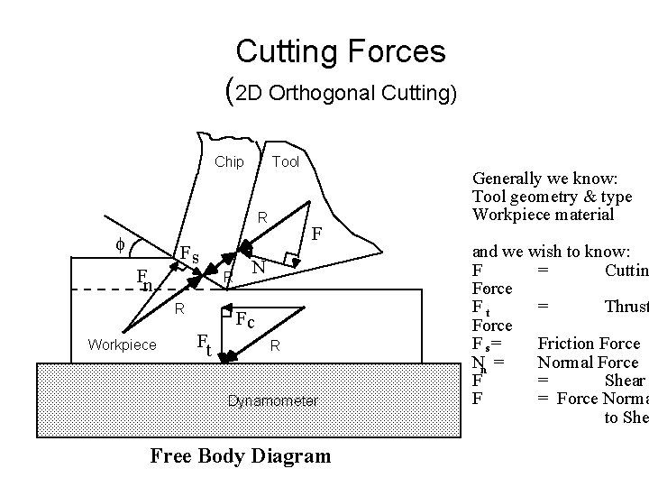
Cutting Forces (2 D Orthogonal Cutting) Chip Tool R f Fn Fs R R Workpiece Ft F N Fc R Dynamometer Free Body Diagram Generally we know: Tool geometry & type Workpiece material and we wish to know: F = Cuttin c Force Ft = Thrust Force F s= Friction Force Nn = Normal Force F = Shear F = Force Norma to She
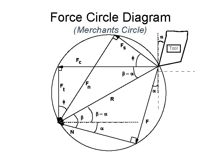
Force Circle Diagram (Merchants Circle) a Fs Tool f Fc b-a F n F t a R f b N b-a F a
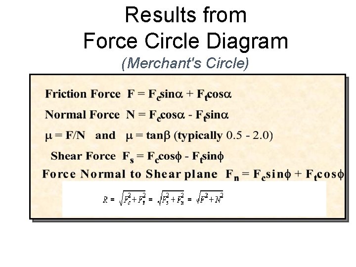
Results from Force Circle Diagram (Merchant's Circle)
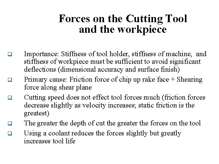
Forces on the Cutting Tool and the workpiece q q q Importance: Stiffness of tool holder, stiffness of machine, and stiffness of workpiece must be sufficient to avoid significant deflections (dimensional accuracy and surface finish) Primary cause: Friction force of chip up rake face + Shearing force along shear plane Cutting speed does not effect tool forces much (friction forces decrease slightly as velocity increases; static friction is the greatest) The greater the depth of cut the greater the forces on the tool Using a coolant reduces the forces slightly but greatly increases tool life
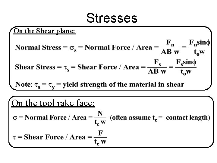
Stresses On the Shear plane: On the tool rake face:
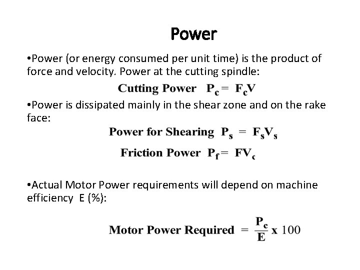
Power • Power (or energy consumed per unit time) is the product of force and velocity. Power at the cutting spindle: • Power is dissipated mainly in the shear zone and on the rake face: • Actual Motor Power requirements will depend on machine efficiency E (%):
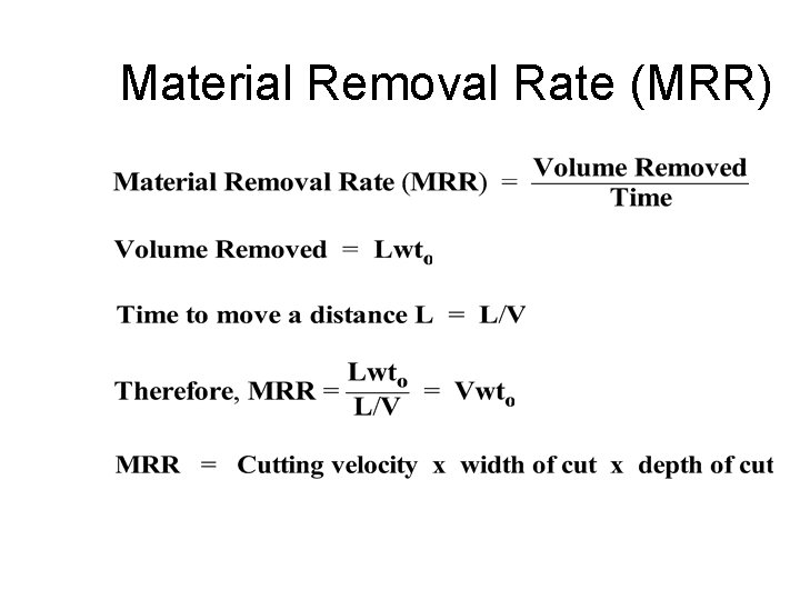
Material Removal Rate (MRR)
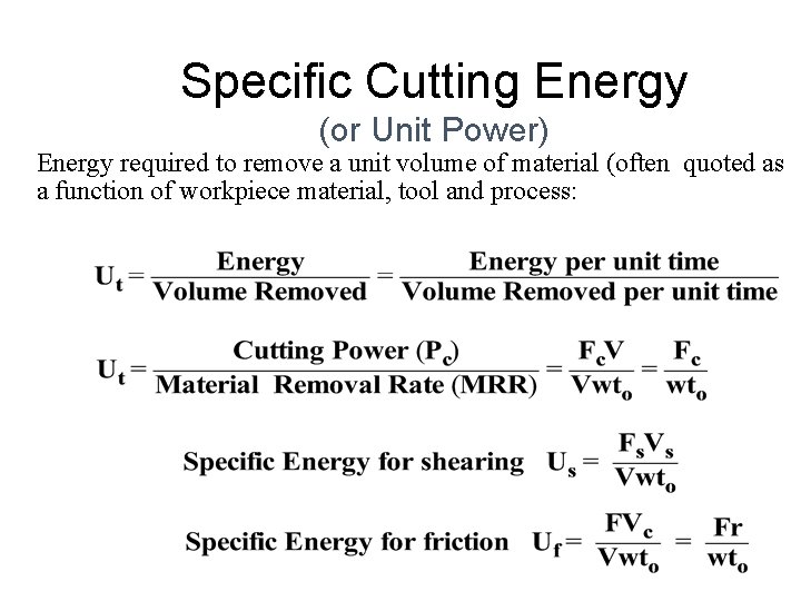
Specific Cutting Energy (or Unit Power) Energy required to remove a unit volume of material (often quoted as a function of workpiece material, tool and process:
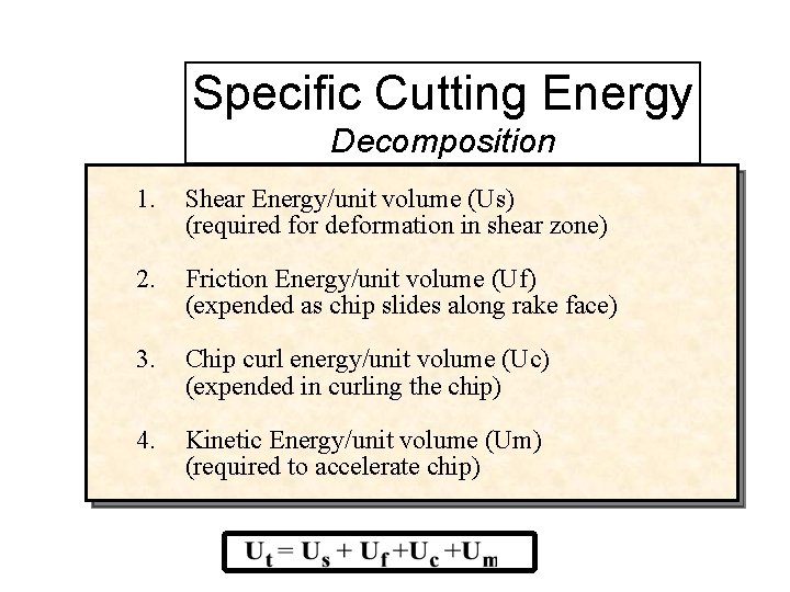
Specific Cutting Energy Decomposition 1. Shear Energy/unit volume (Us) (required for deformation in shear zone) 2. Friction Energy/unit volume (Uf) (expended as chip slides along rake face) 3. Chip curl energy/unit volume (Uc) (expended in curling the chip) 4. Kinetic Energy/unit volume (Um) (required to accelerate chip)
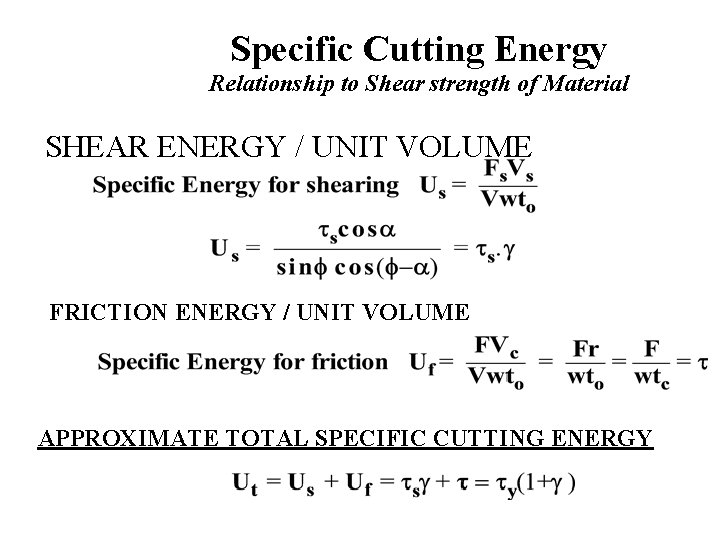
Specific Cutting Energy Relationship to Shear strength of Material SHEAR ENERGY / UNIT VOLUME FRICTION ENERGY / UNIT VOLUME APPROXIMATE TOTAL SPECIFIC CUTTING ENERGY
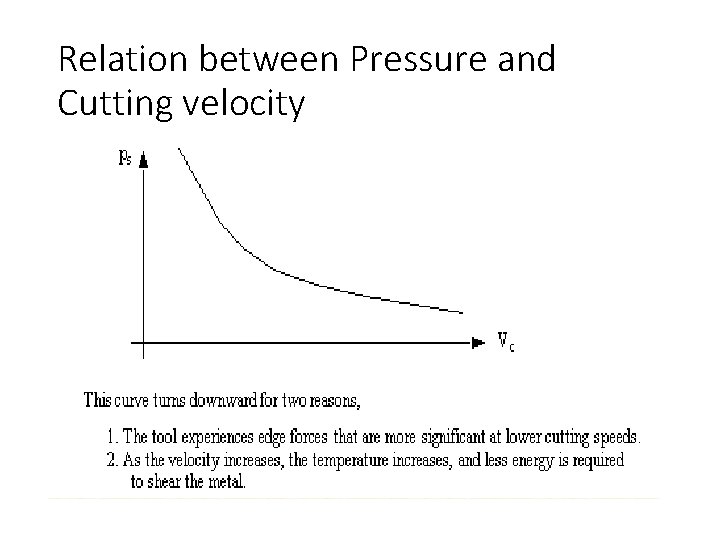
Relation between Pressure and Cutting velocity
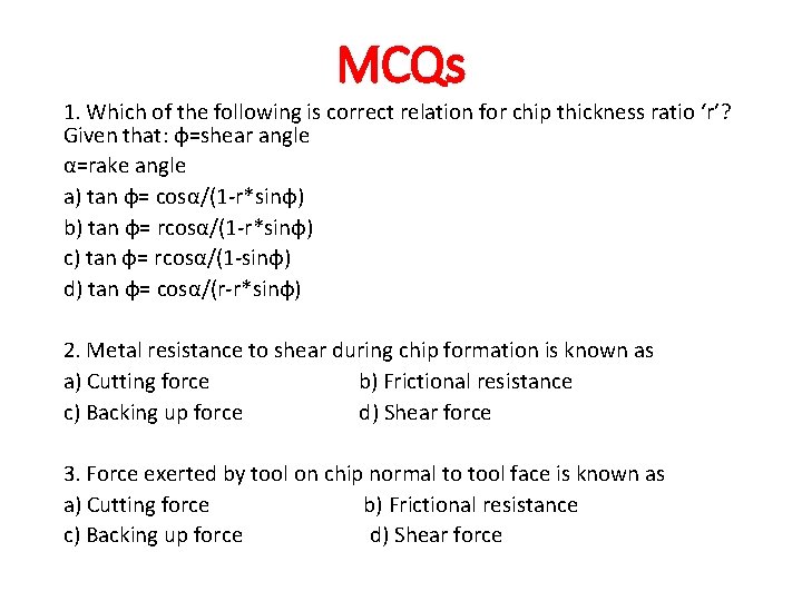
MCQs 1. Which of the following is correct relation for chip thickness ratio ‘r’? Given that: φ=shear angle α=rake angle a) tan φ= cosα/(1 -r*sinφ) b) tan φ= rcosα/(1 -r*sinφ) c) tan φ= rcosα/(1 -sinφ) d) tan φ= cosα/(r-r*sinφ) 2. Metal resistance to shear during chip formation is known as a) Cutting force b) Frictional resistance c) Backing up force d) Shear force 3. Force exerted by tool on chip normal to tool face is known as a) Cutting force b) Frictional resistance c) Backing up force d) Shear force
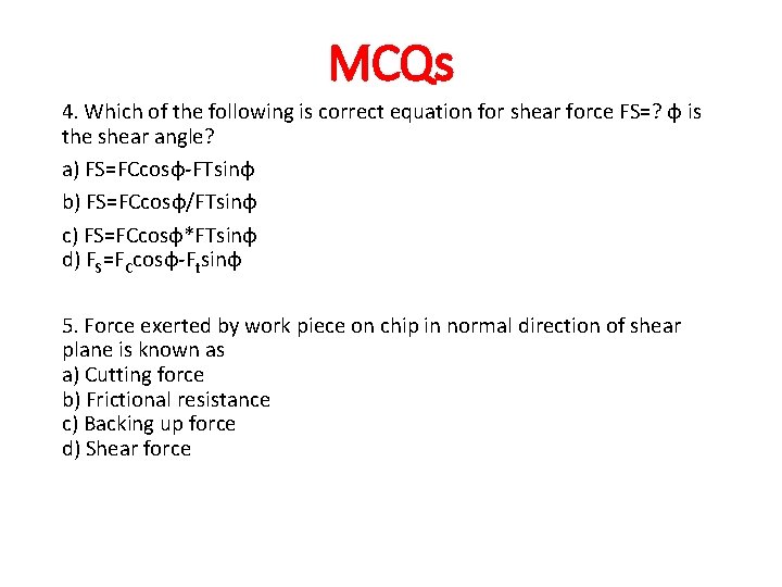
MCQs 4. Which of the following is correct equation for shear force FS=? φ is the shear angle? a) FS=FCcosφ-FTsinφ b) FS=FCcosφ/FTsinφ c) FS=FCcosφ*FTsinφ d) FS=FCcosφ-Ftsinφ 5. Force exerted by work piece on chip in normal direction of shear plane is known as a) Cutting force b) Frictional resistance c) Backing up force d) Shear force