Amperes circuital law I 1 I 2 I


 r 1")


 of the cored coil B 2")
- Slides: 15
Ampere’s circuital law. . I 1. I 2. I 3 The integral of the magnetic field intensity over any contour (the circulation of the field intensity vector) is equal to the algebraic sum of the currents linked with that contour: (1) - Magneto-Motive Force (mmf) (A) For the magnetic circuit excited by a coil carrying current I and having N turns, F = IN 3
Ampere’s circuital law For the most of practical cases of magnetic circuits the integration in Eq. (1) may be replaced with summation, and the Amper’s Circuital Law may be written in a form n – the number of series sections Hk= const – magnetic field intensity in the k-th section k - the length of mean path of k-th section. Ampere’s Circuital Law for the Torus-Form Magnetic Circuit I N 4 R av
Properties of Ferromagnetic Materials 1 The magnetic state of any point in magnetic field is well defined by the magnetic intensity vector and the magnetic induction vector having the same direction. If the magnetic field arises in substantial medium, the relationship B = f(H) is given in a form of B = r 0 H = a H where 0 = 4 10 -7 H m-1 is the magnetic constant, r - is the relative, and a the absolute magnetic permeability, of the substance. 5
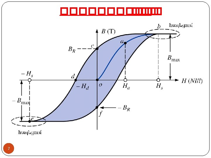
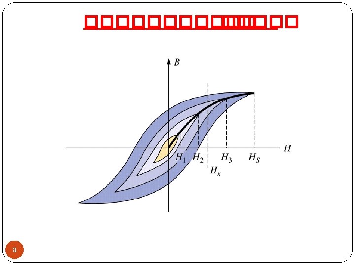
Properties of Ferromagnetic Materials 2 For the most of Materials (Non-Feromagnetic materials) r 1 For Ferromagnetic (or ferrous) materials, r >> 1 Hysteresis Loop of the Ferrous Material B Bm Br Br - Remanence. Hc - Coercitive Force -Hc 0 Hc -Br 6 H 10 Hc For magnetically soft materials Hc < 0, 01 - 0, 05 A m-1 For magnetically hard materials Hc > 20 - 30 k. A m-1.
The Single Path Magnetic Circuit 1 The problem most commonly encountered in the design of a magnetic circuit is to find the mmf F = I N required to excite a magnetic flux (or induction B) within some portion of the magnetic circuit I N I A 2 9 According to the Ampere’s circuital law, A 1 A 2
The Single Path Magnetic Circuit 2 The Magnetic Induction In the Air Gap of the Magnetic Circuit B 0 = 0 H 0 The Magnetic Flux in sections of the Magnetic Circuit B B 2 = B 1 A 1 = B 2 A 2 = B 0 A 0 B 1 B 1= /A 1; 0 10 H 1 H 2 H H B 2= /A 2
Iron-Cored Inductor 1 i ~v 11 e. L N
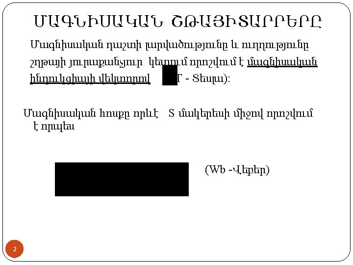
Iron Cored Coil = B A 3 4 0 1 2 i 1 0 2 3 t 4 According to Ampere’s circuital law i 2 3 4 t Weber-Ampere Characteristic = f (i) of the 12
Iron-Cored Inductor 1 i - Main Magnetic Flux m ~v e - Leakage Flux According to KVL E = V = 4. 44 f N m 13
Iron-Cored Inductor 2 ~v r L i e. L e The leakage flux causes a selfinduction emf e. L in the inductor: 0 Idealized iron cored coil According to KVL: 14
Iron-Cored Inductor 3 Weber-Ampere Characteristic = f (i) of the cored coil B 2 i 1 0 2 H 0 3 0 1 4 (A) = B A (Wb) 4 t 15 t 4 i 2 3 3