8251 USART Features 8251 A is a USART


- Slides: 9

8251 USART

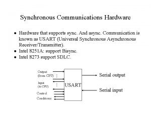
Features 8251 A is a USART (Universal Synchronous Asynchronous Receiver Transmitter) for serial data communication. Programmable peripheral designed for synchronous /asynchronous serial data communication. Receives parallel data from the CPU & transmits serial data after conversion. Also receives serial data from the outside & transmits parallel data to the CPU after conversion.

8251 BLOCK DIAGRAM

Sections of 8251 A • Data Bus buffer • D 0 -D 7 : 8 -bit data bus used to read or write status, command word or data from or to the 8251 A • Read/Write Control Logic • Includes a control logic, six input signals & three buffer registers: Data register, control register & status register. • Control logic : Interfaces the chip with MPU, determines the functions of the chip according to the control word in the control register & monitors the data flow.

CS – Chip Select : When signal goes low, the 8251 A is selected by the MPU for communication. C/D – Control/Data : When signal is high, the control or status register is addressed; when it is low, data buffer is addressed. (Control register & status register are differentiated by WR and RD signals) WR : When signal is low, the MPU either writes in the control register or sends output to the data buffer. RD : When signal goes low, the MPU either reads a status from the status register or accepts data from data buffer. RESET : A high on this signal reset 8252 A & forces it into the idle mode. CLK : Clock input, usually connected to the system clock for communication with the microprocessor.

Control Register 16 -bit register for a control word consist of two independent bytes namely mode word & command word. Mode word : Specifies the general characteristics of operation such as baud, parity, number of bits etc. Command word : Enables the data transmission and reception. Register can be accessed as an output port when the Control/Data pin is high.

Status Register • Checks the ready status of the peripheral. • Status word in the status register provides the information concerning register status and transmission errors. • DATA Register • Used as an input and output port when the C/D is low CS C/D WR RD Operation 0 0 1 1 × 1 0 0 1 × 0 1 1 0 × MPU reads data from data buffer MPU writes a word to control register MPU reads a word from status register Chip is not selected for any operation

Modem Control DSR - Data Set Ready : Checks if the Data Set is ready when communicating with a modem. DTR - Data Terminal Ready : Indicates that the device is ready to accept data when the 8251 is communicating with a modem. CTS - Clear to Send : If its low, the 8251 A is enabled to transmit the serial data provided the enable bit in the command byte is set to ‘ 1’. RTS - Request to Send Data : Low signal indicates the modem that the receiver is ready to receive a data byte from the modem.

Transmitter section Accepts parallel data from MPU & converts them into serial data. Has two registers: Buffer register : To hold eight bits Output register : To convert eight bits into a stream of serial bits. Receiver section Accepts serial data on the Rx. D pin and converts them to parallel data. Has two registers : Receiver input register Buffer register
