THEVENINNORTON THEOREM Definitions and Keywords Thevenin Theorem Any


![Links for further reading [1] “Electrical Engineering Fundamentals”, by Vincent Del Toro, Prenticehall Of Links for further reading [1] “Electrical Engineering Fundamentals”, by Vincent Del Toro, Prenticehall Of](https://slidetodoc.com/presentation_image_h2/8e796b22b5307de4fa242cf38aeadc3f/image-14.jpg)

- Slides: 15

THEVENIN-NORTON THEOREM

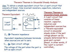
Definitions and Keywords Thevenin Theorem : Any two terminals of a network composed of linear passive and active circuit elements may be replaced by an equivalent voltage source and an equivalent series resistance. The voltage source is equal to the potential difference between the two terminals connected to these terminals. The series resistance is the equivalent resistance looking into the two terminal ports with all the power sources within the terminal pair inactive. Norton Theorem : Any two terminals of a network composed of linear passive and active circuit elements may be replaced by an equivalent current source and a parallel resistance. The current of the source is the current measured in the short circuit placed across the terminal-pair. The parallel resistance is the equivalent resistance looking into the terminalpair with all the independent power sources inactive.

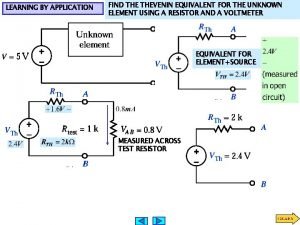
CALCULATING THEVENIN EQUIVALENT To calculate the equivalent circuit, the resistance and voltage are needed, so two equations are required. These two equations are usually obtained by using the following steps, but any conditions placed on the terminals of the circuit should also work: 1. Calculate the output voltage, VAB, when in open circuit condition (no load resistor -meaning infinite resistance). This is VTh. 2. (a) Now replace voltage sources with short circuits and current sources with open circuits. (b) Replace the load circuit with an imaginary ohmmeter and measure the total resistance, R, "looking back" into the circuit. This is RTh.

CALCULATING THE NORTON EQUIVALENT To calculate the equivalent circuit, the resistance and voltage are needed, so two equations are required. These two equations are usually obtained by using the following steps, but any conditions placed on the terminals of the circuit should also work: 1. Find the Norton current INo. Calculate the output current, IAB, with a short circuit as the load (meaning 0 resistance between A and B). This is INo. 2. Find the Norton resistance RNo. When there are no dependent sources (i. e. , all current and voltage sources are independent), there are two methods of determining the Norton impedance RNo. Calculate the output voltage, VAB, when in open circuit condition (i. e. , no load resistor — meaning infinite load resistance). RNo equals this VAB divided by INo. or Replace independent voltage sources with short circuits and independent current sources with open circuits. The total resistance across the output port is the Norton impedance Rno.

Concept details A typical Circuit diagram. 1 2 3 The circuit consists of resistors and a voltage source. Terminals A and B are the terminals across which Thevenin equivalent circuit is to be determined. Current, using an arrow tip, will be circulated across the loop as well as voltage drop across each resistor will be displayed in parallelism. After 1 complete circulation it’s value will be determined and from there the voltage across terminals A and B. Equivalent circuit for determining equivalent output voltage. Equivalent circuit for determining equivalent resistance. The diagram will be morphed into the next equivalent circuit diagram which is the circuit for calculating the equivalent output voltage. Req=R 1+[(R 2+R 3)||R 4] The previous circuit will be morphed into the circuit for determining equivalent resistance. Next the voltage source will be converted into a short. And, equivalent resistance will be calculated using the formula provided.

4 5 6 The final equivalent circuit of the original circuit. Thevenin equivalent circuit. The previous circuit will be morphed into original circuit. Next, all the resistances will be combined together and the equivalent resistance will be displayed in parallelism of changing the value of 15 V to 7. 5 V. A typical Circuit diagram. The circuit consists of resistors and a voltage source. Terminals A and B are the terminals across which Norton equivalent circuit is to be determined. The diagram will be morphed into the next equivalent circuit diagram which is the circuit for calculating the equivalent output voltage. Itotal will be calculated using Kirchhoff's laws. And, finally using the current divider rule I will be calculated. Equivalent circuit for determining equivalent output voltage. =V 1/[R 4+{R 1||(R 2+R 3)}] Using current divider rule: I=[(R 2+R 3)/(R 1+R 2+R 3)]* Itotal

Req= R 1+R 4||(R 2+R 3) 7 8 Equivalent circuit for determining equivalent resistance. The final equivalent circuit of the original circuit. The Norton equivalent circuit. The previous circuit will be morphed into the circuit for determining equivalent resistance. Next the voltage source will be converted into a short. And, equivalent resistance will be calculated using the formula provided. The previous circuit will be morphed into original circuit. Next, all the resistances will be combined together and the equivalent resistance will be displayed in parallelism of changing the value of voltage source from 15 V to current source of 3. 75 m. A.

Interactivity and Boundary limits While determining the Thevenin equivalent of a given circuit the user can alter the value of resistances and sources and observe the changes. Changing the values of the inputs changes the equivalent outputs. None of the resistances or sources should be zero or infinity.

Questionnaire 1. The relation between Thevenin equivalent resistance(RTH) and that of Norton’s (RN) is given by: Answers: a) RTH>RN b) RTH=RN c)RTH<RN d)RTH>>RN

2. In the Thevenin equivalent circuit, the equivalent voltage source is _______ with the equivalent Thevenin resistance. Answer: a)in Parallel b)not connected. c)in series. d)None of them.

3. In the Norton equivalent circuit, the equivalent Norton resistance is _______ with the equivalent Norton current source. Answer: a)in Parallel b)not connected. c)in series. d)None of them.

4. A network has the configuration shown in the figure. All resistance values are expressed in ohms. Find the current through RL when it takes on values of 10, 50 and 200 ohms. Answer: a)0. 324 A, 0. 481 A and 0. 146 A respectively b)0. 481 A, 0. 146 A and 0. 324 A respectively c)0. 481 A, 0. 324 A and 0. 146 A respectively d)None of these.

5. The small signal equivalent of a vacuum-tube amplifier has the configuration depicted in the figure. The indicated circuit parameters have the following values: µ=99, R 1=147, 000 ohms , rp =66, 000 ohms and R 2 =100, 000 ohms. Find the value of the voltage for Eg=0. 4 volt. Answer: a)1. 872 V b)18. 72 V c)11. 42 V d)15. 78 V
![Links for further reading 1 Electrical Engineering Fundamentals by Vincent Del Toro Prenticehall Of Links for further reading [1] “Electrical Engineering Fundamentals”, by Vincent Del Toro, Prenticehall Of](https://slidetodoc.com/presentation_image_h2/8e796b22b5307de4fa242cf38aeadc3f/image-14.jpg)
Links for further reading [1] “Electrical Engineering Fundamentals”, by Vincent Del Toro, Prenticehall Of India Pvt. Ltd. [2] “Basic Electrical Engineering”, by D. P. Kothari and I. J. Nagrath, Tata Mc. Graw-Hill Publishing Pvt. Ltd.

Thank you Made by: - Rutesh Chavda
 Thevenin theorem
 Difference between superposition and thevenin theorem
 Thevenin’s theorem is true for
 Objective of thevenin theorem
 Thevenin's theorem solved problems dc circuits
 Thevenin theorem derivation
 Use source transformation to find the value
 Nilsson riedel
 Ece 271
 Norton
 Teorema thevenin dan norton
 Stoke's theorem
 Some any cheese
 Any to any connectivity
 Any question atau any questions
 Thevenin equivalent equations
