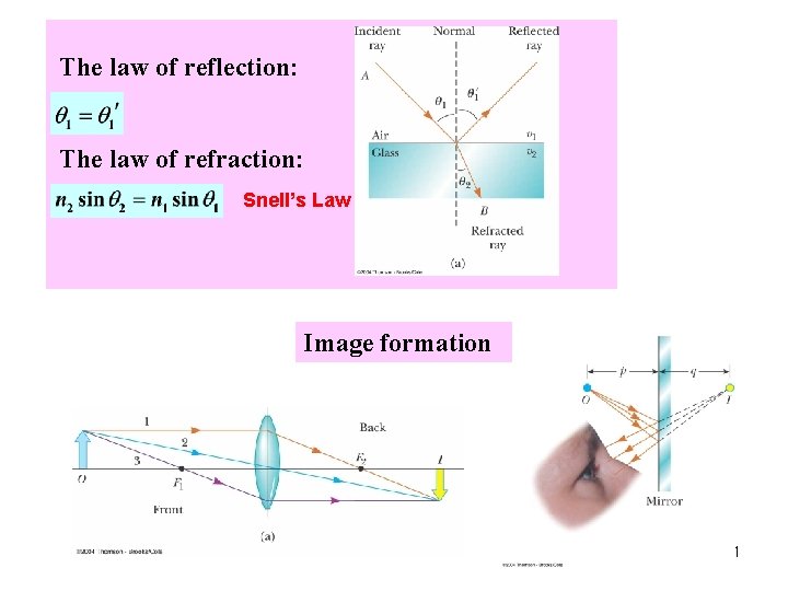
The law of reflection The law of refraction
- Slides: 48
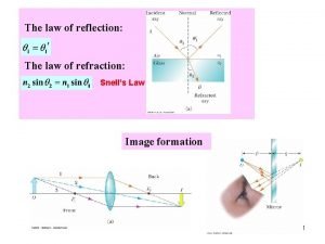
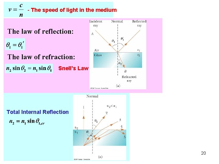
The law of reflection: The law of refraction: Snell’s Law Image formation 1
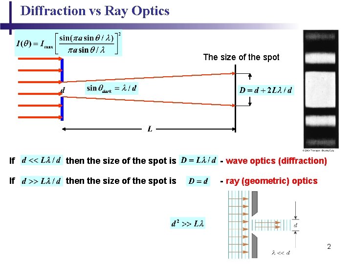
Diffraction vs Ray Optics The size of the spot If then the size of the spot is - wave optics (diffraction) If then the size of the spot is - ray (geometric) optics 2
Chapter 18 Propagation of Light - Ray Optics 3
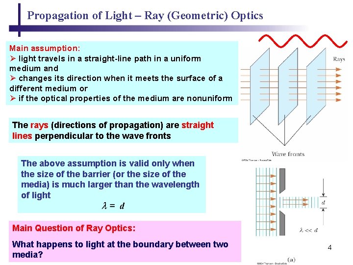
Propagation of Light – Ray (Geometric) Optics Main assumption: Ø light travels in a straight-line path in a uniform medium and Ø changes its direction when it meets the surface of a different medium or Ø if the optical properties of the medium are nonuniform The rays (directions of propagation) are straight lines perpendicular to the wave fronts The above assumption is valid only when the size of the barrier (or the size of the media) is much larger than the wavelength of light Main Question of Ray Optics: What happens to light at the boundary between two media? 4
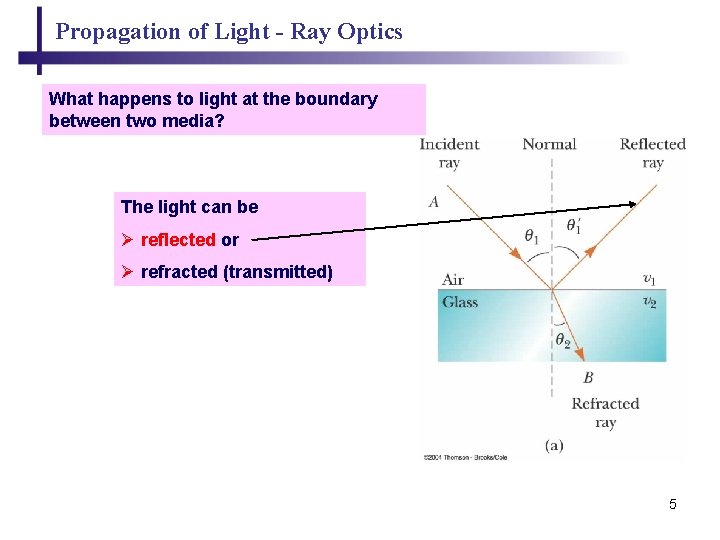
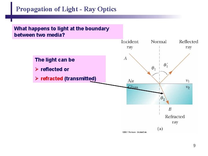
Propagation of Light - Ray Optics What happens to light at the boundary between two media? The light can be Ø reflected or Ø refracted (transmitted) 5
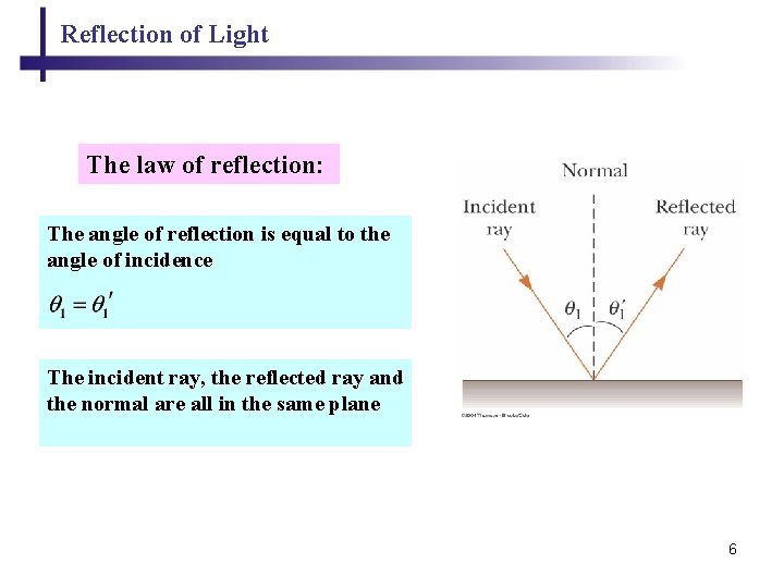
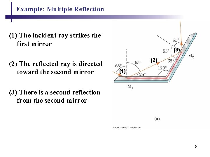
Reflection of Light The law of reflection: The angle of reflection is equal to the angle of incidence The incident ray, the reflected ray and the normal are all in the same plane 6
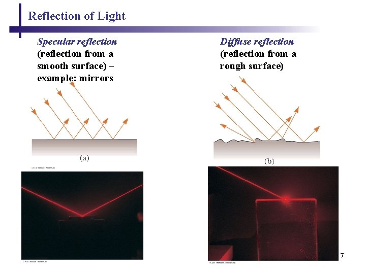
Reflection of Light Specular reflection (reflection from a smooth surface) – example: mirrors Diffuse reflection (reflection from a rough surface) 7
Example: Multiple Reflection (1) The incident ray strikes the first mirror (2) The reflected ray is directed toward the second mirror (3) (2) (1) (3) There is a second reflection from the second mirror 8
Propagation of Light - Ray Optics What happens to light at the boundary between two media? The light can be Ø reflected or Ø refracted (transmitted) 9
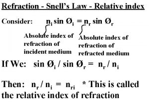
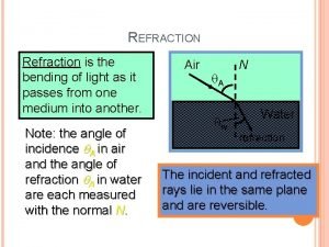
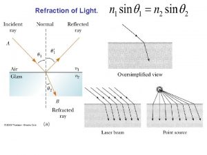
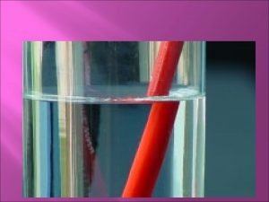
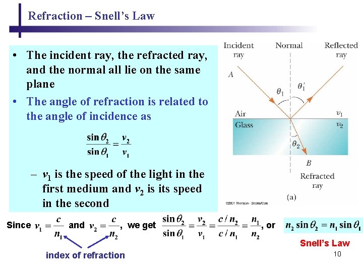
Refraction – Snell’s Law • The incident ray, the refracted ray, and the normal all lie on the same plane • The angle of refraction is related to the angle of incidence as – v 1 is the speed of the light in the first medium and v 2 is its speed in the second Since and , we get , or Snell’s Law index of refraction 10
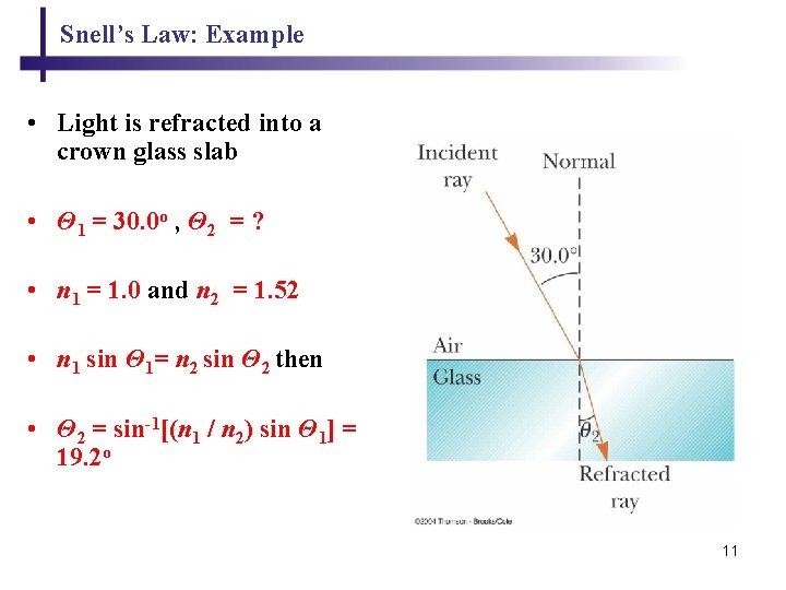
Snell’s Law: Example • Light is refracted into a crown glass slab • Θ 1 = 30. 0 o , Θ 2 = ? • n 1 = 1. 0 and n 2 = 1. 52 • n 1 sin Θ 1= n 2 sin Θ 2 then • Θ 2 = sin-1[(n 1 / n 2) sin Θ 1] = 19. 2 o 11
Refraction in a Prism 12
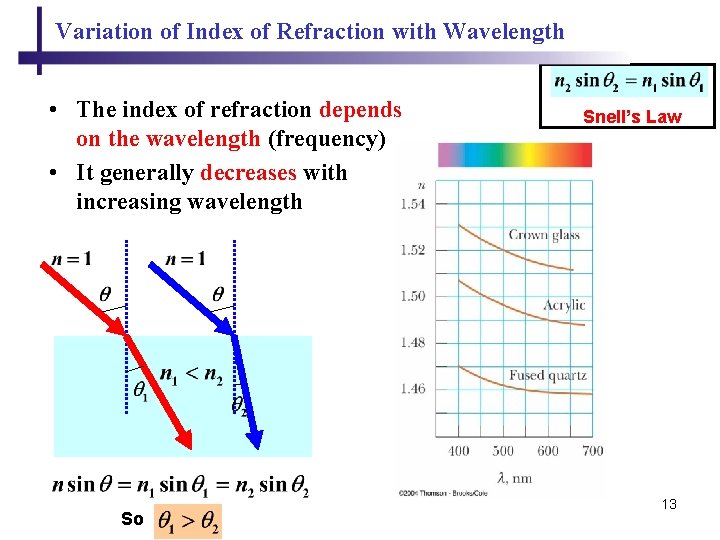
Variation of Index of Refraction with Wavelength • The index of refraction depends on the wavelength (frequency) • It generally decreases with increasing wavelength So Snell’s Law 13
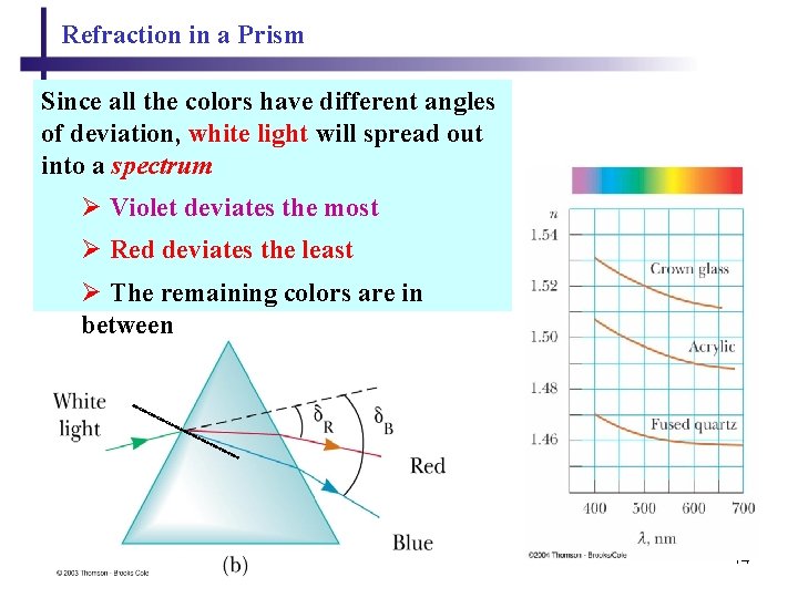
Refraction in a Prism Since all the colors have different angles of deviation, white light will spread out into a spectrum Ø Violet deviates the most Ø Red deviates the least Ø The remaining colors are in between 14
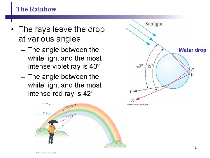
The Rainbow • The rays leave the drop at various angles – The angle between the white light and the most intense violet ray is 40° – The angle between the white light and the most intense red ray is 42° Water drop 15
Total Internal Reflection 16
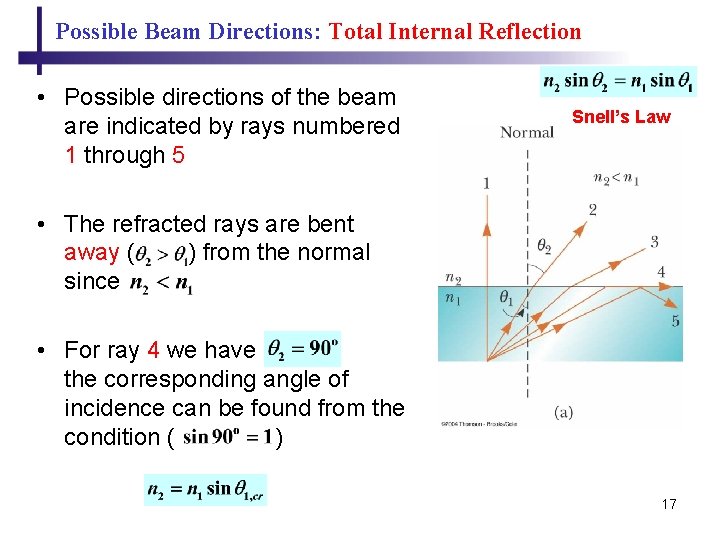
Possible Beam Directions: Total Internal Reflection • Possible directions of the beam are indicated by rays numbered 1 through 5 Snell’s Law • The refracted rays are bent away ( ) from the normal since • For ray 4 we have the corresponding angle of incidence can be found from the condition ( ) 17
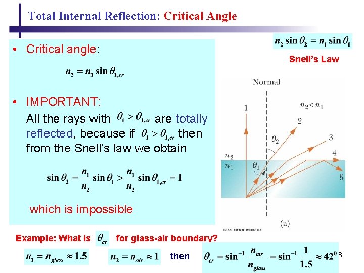
Total Internal Reflection: Critical Angle • Critical angle: Snell’s Law • IMPORTANT: All the rays with are totally reflected, because if then from the Snell’s law we obtain which is impossible Example: What is for glass-air boundary? then 18
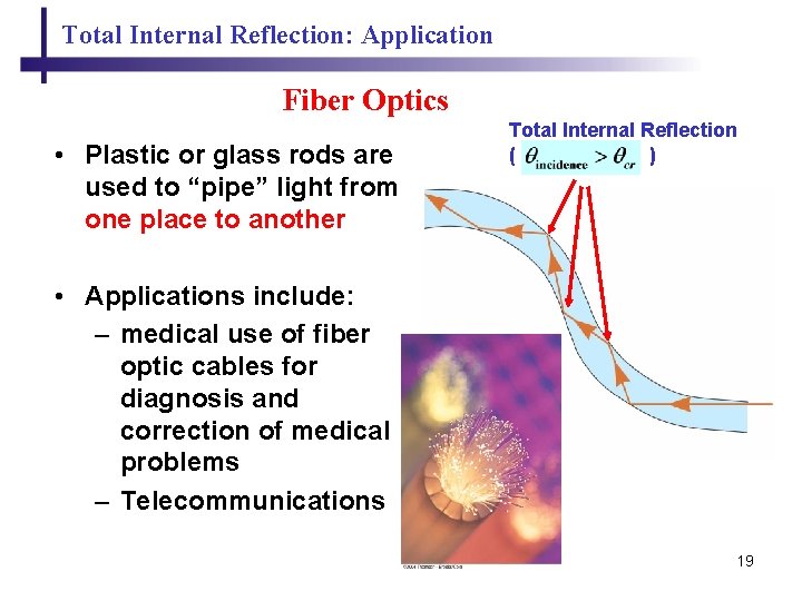
Total Internal Reflection: Application Fiber Optics • Plastic or glass rods are used to “pipe” light from one place to another Total Internal Reflection ( ) • Applications include: – medical use of fiber optic cables for diagnosis and correction of medical problems – Telecommunications 19
- The speed of light in the medium The law of reflection: The law of refraction: Snell’s Law Total Internal Reflection 20
Chapter 18 Ray Optics - Applications: Image Formation 21
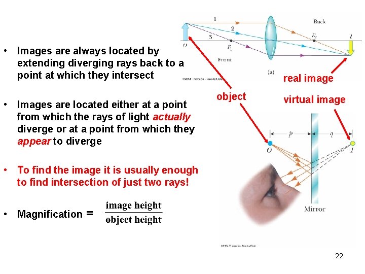
• Images are always located by extending diverging rays back to a point at which they intersect • Images are located either at a point from which the rays of light actually diverge or at a point from which they appear to diverge real image object virtual image • To find the image it is usually enough to find intersection of just two rays! • Magnification = 22
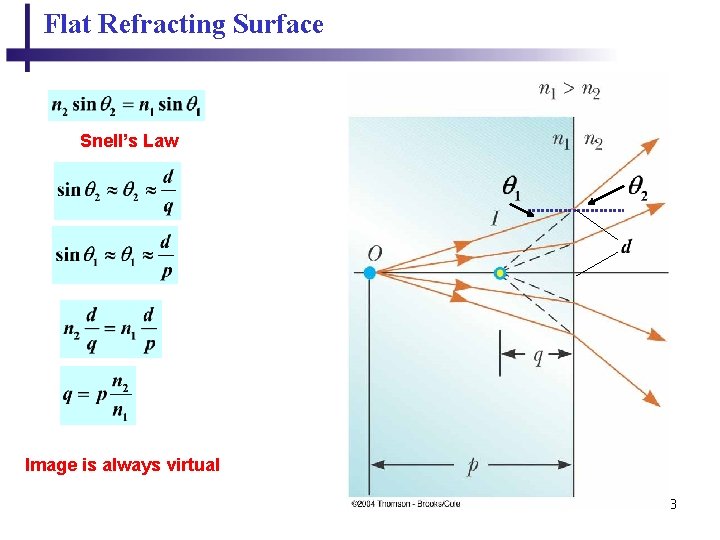
Flat Refracting Surface Snell’s Law Image is always virtual 23
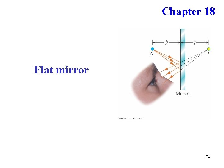
Chapter 18 Flat mirror 24
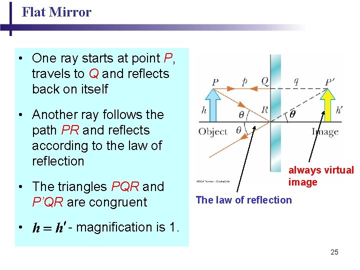
Flat Mirror • One ray starts at point P, travels to Q and reflects back on itself • Another ray follows the path PR and reflects according to the law of reflection • The triangles PQR and P’QR are congruent • . always virtual image The law of reflection - magnification is 1. 25
Chapter 18 Geometric Optics - Applications: Thin Lenses 26
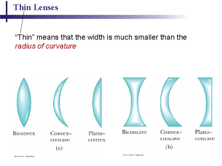
Thin Lenses “Thin” means that the width is much smaller than the radius of curvature 27
Thin Lenses: Focal Points 28
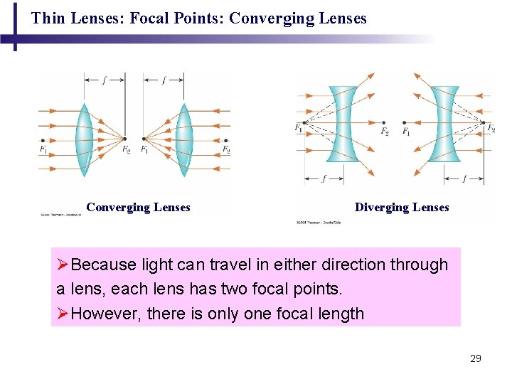
Thin Lenses: Focal Points: Converging Lenses Diverging Lenses ØBecause light can travel in either direction through a lens, each lens has two focal points. ØHowever, there is only one focal length 29
Thin Lenses: Ray Diagram 30
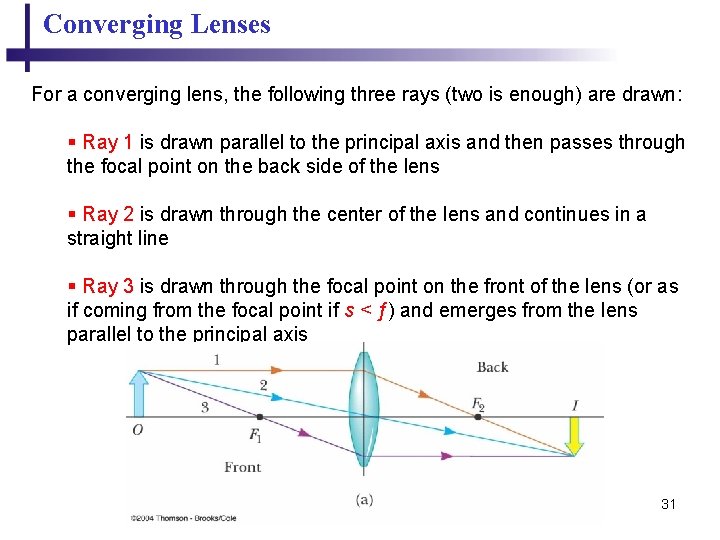
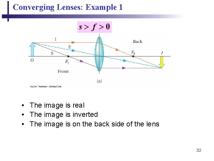
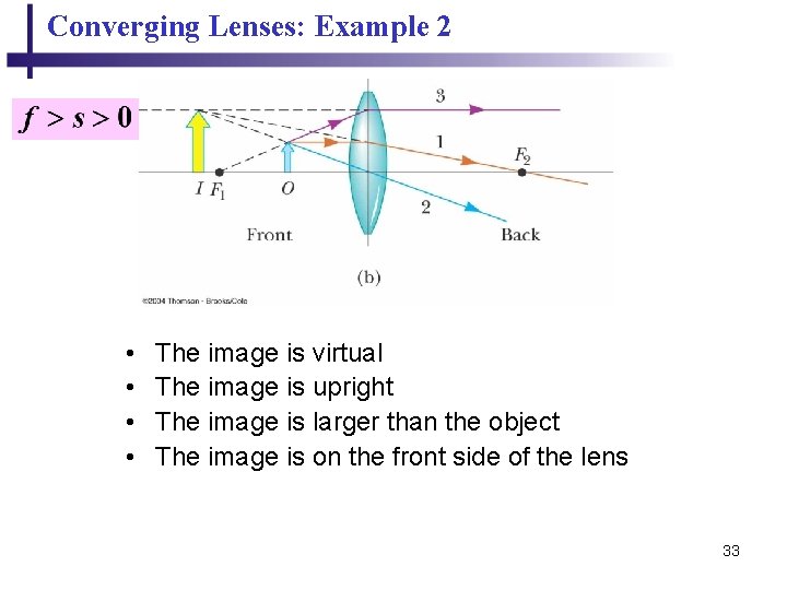
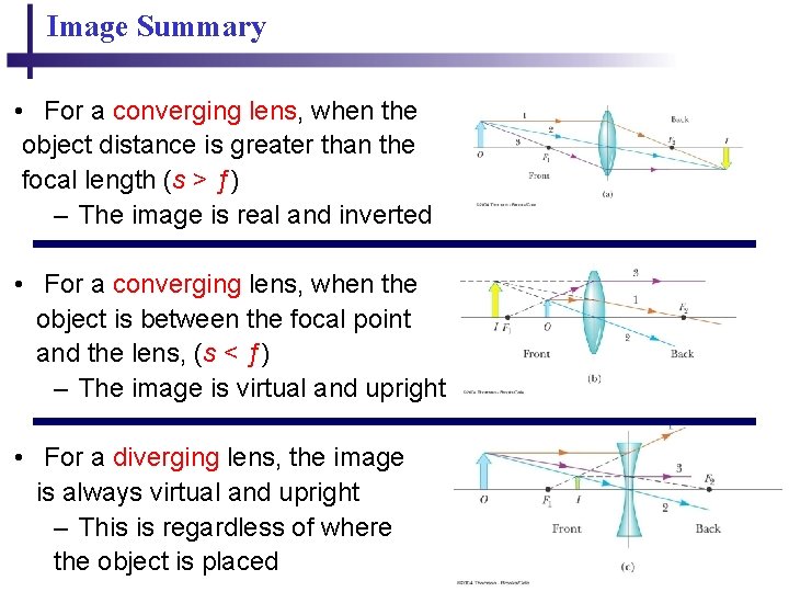
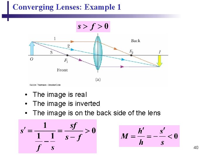
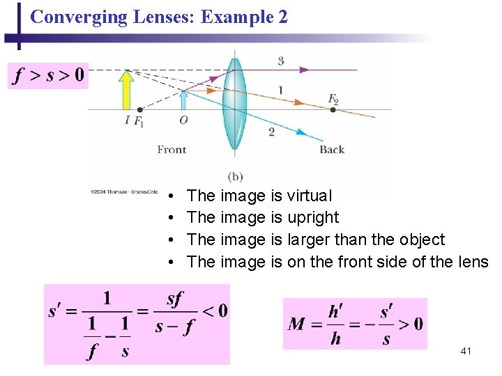
Converging Lenses For a converging lens, the following three rays (two is enough) are drawn: § Ray 1 is drawn parallel to the principal axis and then passes through the focal point on the back side of the lens § Ray 2 is drawn through the center of the lens and continues in a straight line § Ray 3 is drawn through the focal point on the front of the lens (or as if coming from the focal point if s < ƒ) and emerges from the lens parallel to the principal axis 31
Converging Lenses: Example 1 • The image is real • The image is inverted • The image is on the back side of the lens 32
Converging Lenses: Example 2 • • The image is virtual The image is upright The image is larger than the object The image is on the front side of the lens 33
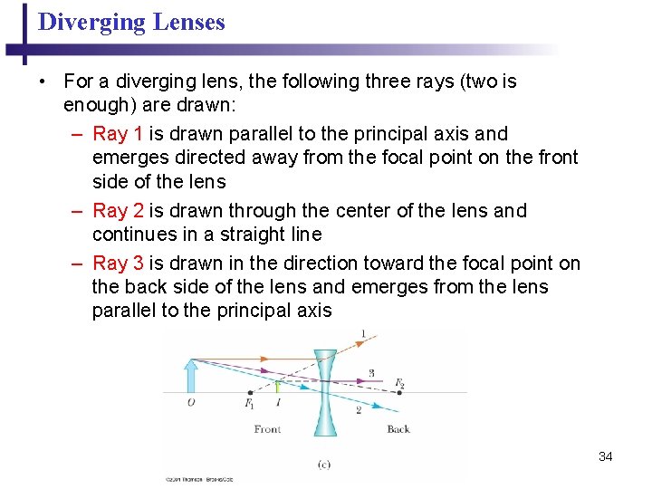
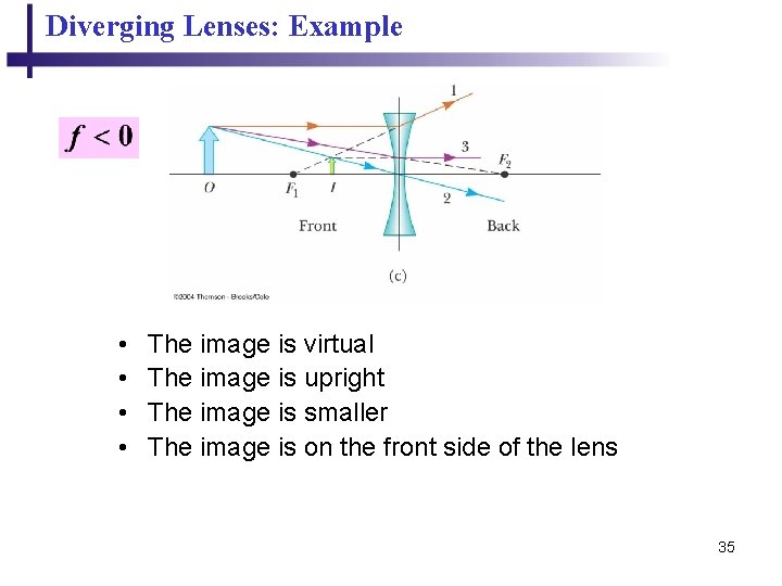
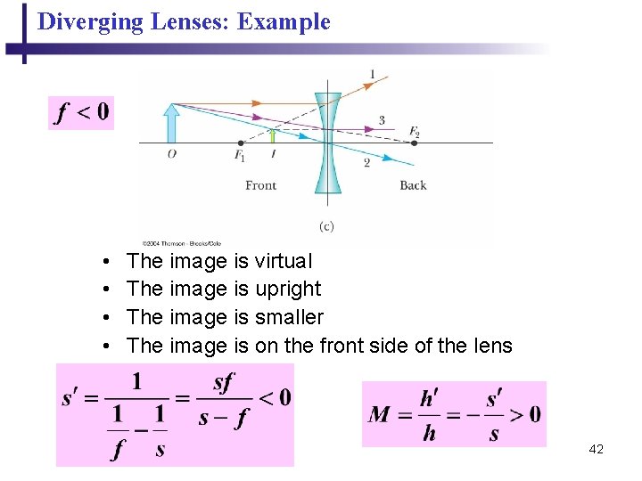
Diverging Lenses • For a diverging lens, the following three rays (two is enough) are drawn: – Ray 1 is drawn parallel to the principal axis and emerges directed away from the focal point on the front side of the lens – Ray 2 is drawn through the center of the lens and continues in a straight line – Ray 3 is drawn in the direction toward the focal point on the back side of the lens and emerges from the lens parallel to the principal axis 34
Diverging Lenses: Example • • The image is virtual The image is upright The image is smaller The image is on the front side of the lens 35
Image Summary • For a converging lens, when the object distance is greater than the focal length (s > ƒ) – The image is real and inverted • For a converging lens, when the object is between the focal point and the lens, (s < ƒ) – The image is virtual and upright • For a diverging lens, the image is always virtual and upright – This is regardless of where the object is placed 36
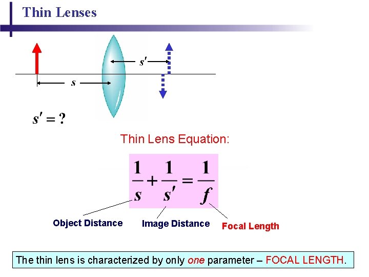
Thin Lenses Thin Lens Equation: Object Distance Image Distance Focal Length 37 The thin lens is characterized by only one parameter – FOCAL LENGTH.
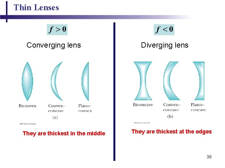
Thin Lenses Converging lens They are thickest in the middle Diverging lens They are thickest at the edges 38
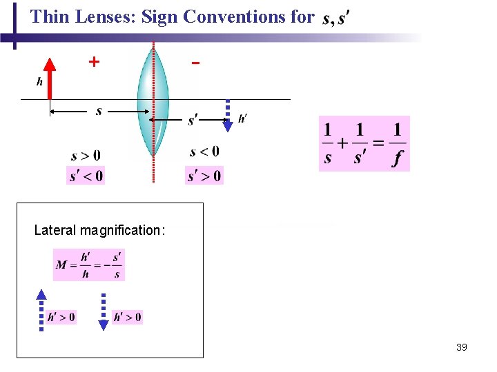
Thin Lenses: Sign Conventions for s, s + - Lateral magnification: 39
Converging Lenses: Example 1 • The image is real • The image is inverted • The image is on the back side of the lens 40
Converging Lenses: Example 2 • • The image is virtual The image is upright The image is larger than the object The image is on the front side of the lens 41
Diverging Lenses: Example • • The image is virtual The image is upright The image is smaller The image is on the front side of the lens 42
Combination of Two Lenses 43
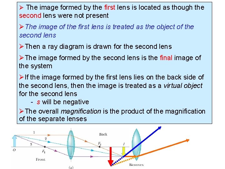
Ø The image formed by the first lens is located as though the second lens were not present ØThe image of the first lens is treated as the object of the second lens ØThen a ray diagram is drawn for the second lens ØThe image formed by the second lens is the final image of the system ØIf the image formed by the first lens lies on the back side of the second lens, then the image is treated as a virtual object for the second lens - s will be negative ØThe overall magnification is the product of the magnification of the separate lenses 44
Resolution 45
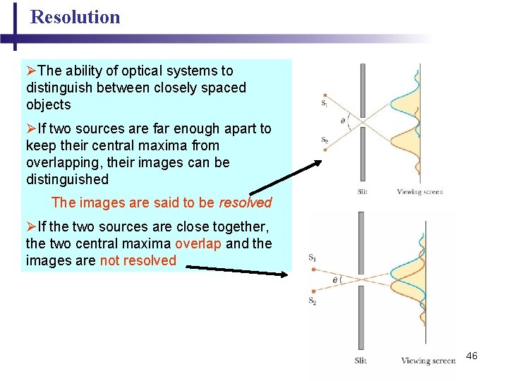
Resolution ØThe ability of optical systems to distinguish between closely spaced objects ØIf two sources are far enough apart to keep their central maxima from overlapping, their images can be distinguished The images are said to be resolved ØIf the two sources are close together, the two central maxima overlap and the images are not resolved 46
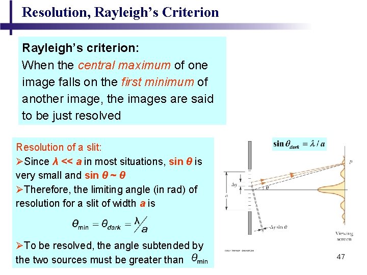
Resolution, Rayleigh’s Criterion Rayleigh’s criterion: When the central maximum of one image falls on the first minimum of another image, the images are said to be just resolved Resolution of a slit: ØSince λ << a in most situations, sin θ is very small and sin θ ~ θ ØTherefore, the limiting angle (in rad) of resolution for a slit of width a is ØTo be resolved, the angle subtended by the two sources must be greater than 47
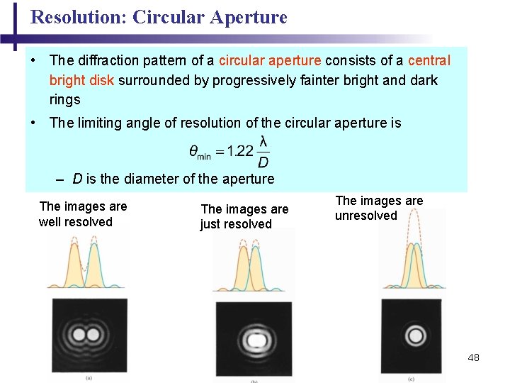
Resolution: Circular Aperture • The diffraction pattern of a circular aperture consists of a central bright disk surrounded by progressively fainter bright and dark rings • The limiting angle of resolution of the circular aperture is – D is the diameter of the aperture The images are well resolved The images are just resolved The images are unresolved 48