TAPI Photonic Model OMS and OTS layers Andrea



- Slides: 13
TAPI Photonic Model OMS and OTS layers Andrea Mazzini, Nokia November 15, 2019
Purpose of this contribution • Evaluate possible alternative models for the Physical, OSC, OMS and OTS layers. • Define some simple rules concerning encapsulation. • References are Core IM v 1. 4 and otcc 2019. SSL. 004_TAPI Photonic. Media. Model. pptx
Full View of the Model (ROADM to ROADM node) - otcc 2019. SSL. 004_TAPI Photonic. Media. Model MC Link (L band) MC MC Link (C band) OMS (L band) OMS (C band) OTS OSC OMS (C band) OMS Link (L band) OMS Link (C band) OTS (L band) OTS (C band) OTS Link OSC OSC Link PHY C (ILA) A (ROADM) Degree Port ILA Port 3 ILA Port Topology = n 1 B (ROADM) Degree Port
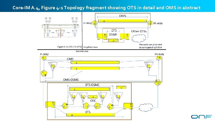
Core-IM A. 4, Figure 4 -1 Topology fragment showing OTS in detail and OMS in abstract (assuming EDFA) 4
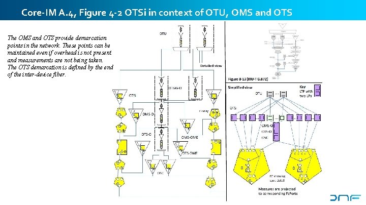
Core-IM A. 4, Figure 4 -2 OTSi in context of OTU, OMS and OTS The OMS and OTS provide demarcation points in the network. These points can be maintained even if overhead is not present and measurements are not being taken. The OTS demarcation is defined by the end of the inter-device fiber. 5
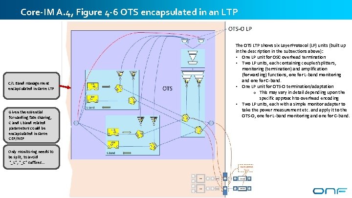
Core-IM A. 4, Figure 4 -6 OTS encapsulated in an LTP The OTS LTP shows six Layer. Protocol (LP) units (built up in the description in the subsections above): • One LP unit for OSC overhead termination • Two LP units, each containing coupler/splitters, monitoring (termination) and amplification (forwarding) functions, one for L-band monitoring and one for C-band. • One LP unit for OTS-O termination/adaptation o This may vary in detail depending upon the specific approach to overhead encoding • Two LP units, each with a simple monitor adapter to take the power measurement etc. and apply it to the OTS-O, one for L-band monitoring and one for C-band. C/L Band management encapsulated in same LTP Given the essential forwarding fate sharing, C and L band related parameters could be encapsulated in same CEP/NEP Only monitoring needs to be split, to avoid “_L”, “_C” suffixes… 6
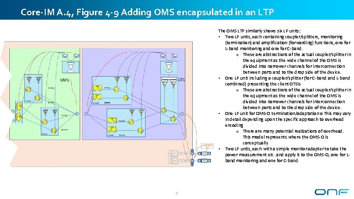
Core-IM A. 4, Figure 4 -9 Adding OMS encapsulated in an LTP The OMS LTP similarly shows six LP units: • Two LP units, each containing coupler/splitters, monitoring (termination) and amplification (forwarding) functions, one for L-band monitoring and one for C-band. o These are abstractions of the actual coupler/splitter in the equipment as the wide channel of the OMS is divided into narrower channels for interconnection between ports and to the drop side of the device. • One LP unit including a coupler/splitter (for C-band L-band combined) presenting the client OTSis o These are abstractions of the actual coupler/splitter in the equipment as the wide channel of the OMS is divided into narrower channels for interconnection between ports and to the drop side of the device. • One LP unit for OMS-O termination/adaptation o This may vary in detail depending upon the specific approach to overhead encoding o There are many potential realizations of overhead. This model represents where the OMS-O is conceptually • Two LP units, each with a simple monitor adapter to take the power measurement etc. and apply it to the OMS-O, one for Lband monitoring and one for C-band. 7
ROADM to ILA – backward compatibility, keeping OTS and OMS MC Link (L band) MC MC Link (C band) OMS (L band) OMS (C band) OMS Link (L band) OMS Link (C band) OSC PHY OTS (L band) OTS (C band) OTS Link C (ILA) A (ROADM) Degree Port ILA Port 8
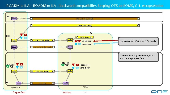
ROADM to ILA – backward compatibility, keeping OTS and OMS, C+L encapsulation MC MC Link (C&L band) OMS OMS (C&L) OMS (C&L band) L OMS-O MIP Separated MEP/MIP for C / L bands C OMS-O MIP OMS Link (C&L band) From forwarding viewpoint, band C and L always share fate. OSC PHY L OTS-O MEP C OTS-O MEP OTS (C&L band) OTS Link C (ILA) A (ROADM) Degree Port ILA Port 9
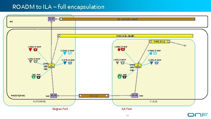
ROADM to ILA – full encapsulation MC Link (C&L band) MC OMS (C&L band) OMS (C+L) L OMS-O MIP L OMS-O MEP C OMS-O MIP C OMS-O MEP L OTS-O MEP C OTS-O MEP OMS OTS PHY OSC PHY PHY/OTS/OMS PHY Link PHY A (ROADM) C (ILA) Degree Port ILA Port 10
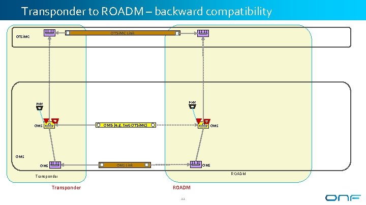
Transponder to ROADM – backward compatibility OTSi. MC Link OTSi. MC PHY OMS (e. g. two OTSi. MC) OMS OMS Link OMS ROADM Transponder ROADM 11
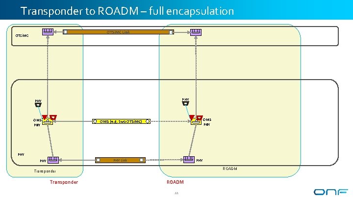
Transponder to ROADM – full encapsulation OTSi. MC Link OTSi. MC PHY OMS (e. g. two OTSi. MC) PHY Link PHY ROADM Transponder ROADM 12
Encapsulation OMS Layer Protocol F Device OTS Layer Protocol Node. Edge. Point Connection. End. Point X Service. Interface. Point Connection Link Connection* Link Transitional Link F PHY Layer Protocol F Layer Protocol 13