System Level Performance Comparison of Interlaced Pilots and

- Slides: 13
System Level Performance Comparison of Interlaced Pilots and Pilot-on-Pilots Document Number: IEEE C 80216 m-09_0039 r 1 Date Submitted: 2009 -01 -05 Source: Kiran Kuchi, J. Klutto Milleth, Vinod R, Dileep M K, Divagar , Padmanabhan M S, Bhaskar R, Giridhar K CEWi. T, India Voice: E-mail: kkuchi@cewit. org. in, klutto@cewit. org. in Venue: San Diego, USA. In response to the TGm Call for Contributions and Comments IEEE 802. 16 m-08/053 r 1 for amendment text Session 59 Topic TGm amendment working document text - section 11. 5. 3 (DL Pilots ) Base Contribution: IEEE C 80216 m-09_0039 Purpose: Presentation associated with comment tgmsdd_Kuchi_Kiran. cmtb To discuss in TGm for appropriate action. Notice: This document does not represent the agreed views of the IEEE 802. 16 Working Group or any of its subgroups. It represents only the views of the participants listed in the “Source(s)” field above. It is offered as a basis for discussion. It is not binding on the contributor(s), who reserve(s) the right to add, amend or withdraw material contained herein. Release: The contributor grants a free, irrevocable license to the IEEE to incorporate material contained in this contribution, and any modifications thereof, in the creation of an IEEE Standards publication; to copyright in the IEEE’s name any IEEE Standards publication even though it may include portions of this contribution; and at the IEEE’s sole discretion to permit others to reproduce in whole or in part the resulting IEEE Standards publication. The contributor also acknowledges and accepts that this contribution may be made public by IEEE 802. 16. Patent Policy: The contributor is familiar with the IEEE-SA Patent Policy and Procedures: <http: //standards. ieee. org/guides/bylaws/sect 6 -7. html#6> and <http: //standards. ieee. org/guides/opman/sect 6. html#6. 3>. Further information is located at <http: //standards. ieee. org/board/pat-material. html> and <http: //standards. ieee. org/board/pat >.
Presentation Outline Pilot-on-Pilot Vs Pilot-on-Data (Interlaced Pilots) Proposed Downlink Pilot Structure for Cell Edge Users Performance comparison Proposed Text
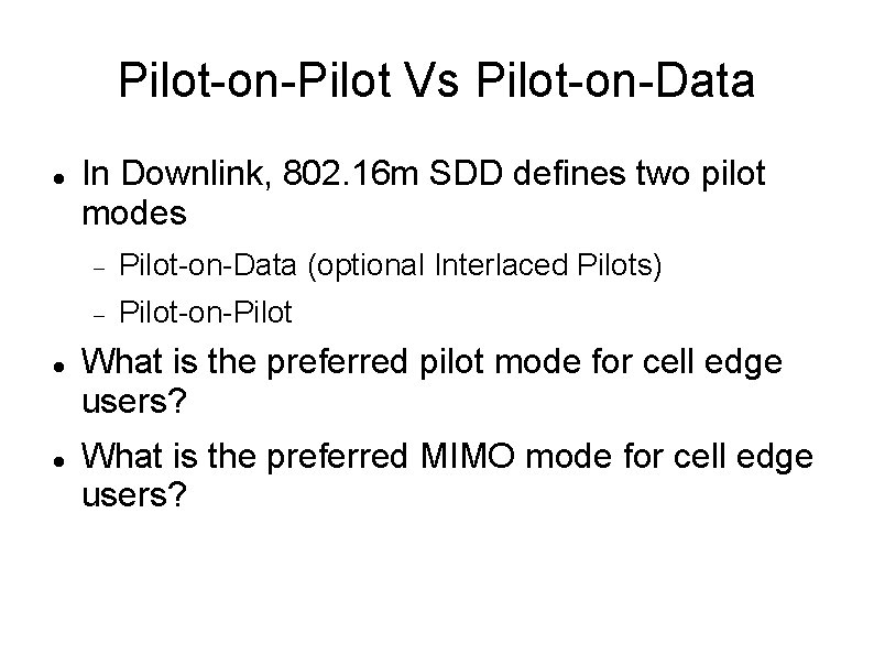
Pilot-on-Pilot Vs Pilot-on-Data In Downlink, 802. 16 m SDD defines two pilot modes Pilot-on-Data (optional Interlaced Pilots) Pilot-on-Pilot What is the preferred pilot mode for cell edge users? What is the preferred MIMO mode for cell edge users?
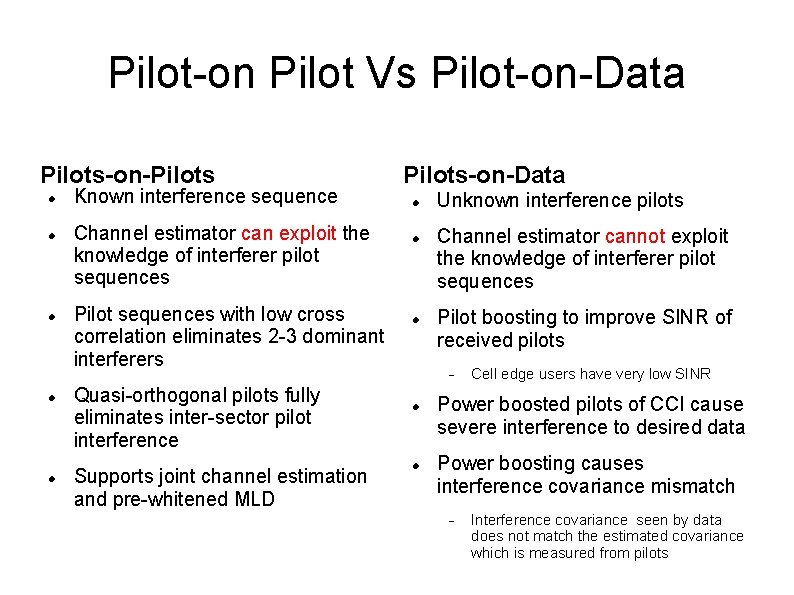
Pilot-on Pilot Vs Pilot-on-Data Pilots-on-Pilots Known interference sequence Channel estimator can exploit the knowledge of interferer pilot sequences Pilot sequences with low cross correlation eliminates 2 -3 dominant interferers Quasi-orthogonal pilots fully eliminates inter-sector pilot interference Supports joint channel estimation and pre-whitened MLD Pilots-on-Data Unknown interference pilots Channel estimator cannot exploit the knowledge of interferer pilot sequences Pilot boosting to improve SINR of received pilots Cell edge users have very low SINR Power boosted pilots of CCI cause severe interference to desired data Power boosting causes interference covariance mismatch Interference covariance seen by data does not match the estimated covariance which is measured from pilots
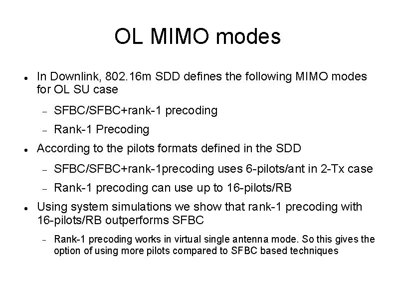
OL MIMO modes In Downlink, 802. 16 m SDD defines the following MIMO modes for OL SU case SFBC/SFBC+rank-1 precoding Rank-1 Precoding According to the pilots formats defined in the SDD SFBC/SFBC+rank-1 precoding uses 6 -pilots/ant in 2 -Tx case Rank-1 precoding can use up to 16 -pilots/RB Using system simulations we show that rank-1 precoding with 16 -pilots/RB outperforms SFBC Rank-1 precoding works in virtual single antenna mode. So this gives the option of using more pilots compared to SFBC based techniques
What is the Pilot Density Requirement for Cell Edge CDR Users?
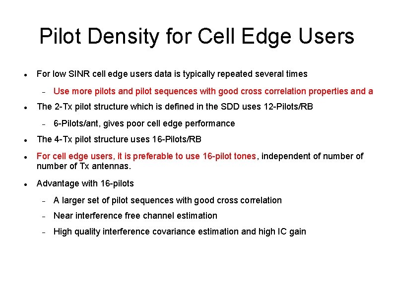
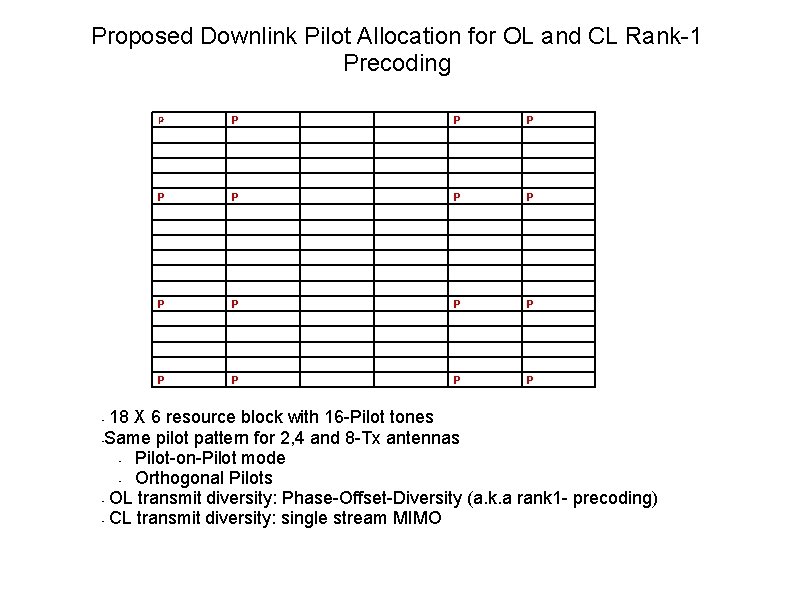
Pilot Density for Cell Edge Users For low SINR cell edge users data is typically repeated several times The 2 -Tx pilot structure which is defined in the SDD uses 12 -Pilots/RB Use more pilots and pilot sequences with good cross correlation properties and a 6 -Pilots/ant, gives poor cell edge performance The 4 -Tx pilot structure uses 16 -Pilots/RB For cell edge users, it is preferable to use 16 -pilot tones, independent of number of Tx antennas. Advantage with 16 -pilots A larger set of pilot sequences with good cross correlation Near interference free channel estimation High quality interference covariance estimation and high IC gain
Proposed Downlink Pilot Allocation for OL and CL Rank-1 Precoding P P P P 18 X 6 resource block with 16 -Pilot tones • Same pilot pattern for 2, 4 and 8 -Tx antennas • Pilot-on-Pilot mode • Orthogonal Pilots • OL transmit diversity: Phase-Offset-Diversity (a. k. a rank 1 - precoding) • CL transmit diversity: single stream MIMO •
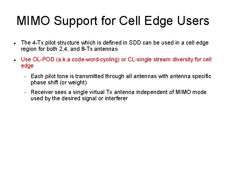
MIMO Support for Cell Edge Users The 4 -Tx pilot structure which is defined in SDD can be used in a cell edge region for both 2, 4, and 8 -Tx antennas Use OL-POD (a. k. a code-word-cycling) or CL-single stream diversity for cell edge Each pilot tone is transmitted through all antennas with antenna specific phase shift (or weight) Receiver sees a single virtual Tx antenna independent of MIMO mode used by the desired signal or interferer
System Level Performance Evaluation for Cell Edge Users
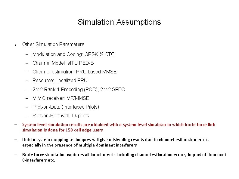
Simulation Assumptions Other Simulation Parameters – Modulation and Coding: QPSK ½ CTC – Channel Model: e. ITU PED-B – Channel estimation: PRU based MMSE – Resource: Localized PRU – 2 x 2 Rank-1 Precoding (POD), 2 x 2 SFBC – MIMO receiver: MF/MMSE – Pilot-on-Data (Interlaced Pilots) – Pilot-on-Pilot with 16 -pilots – System level simulation results are obtained with a system level simulator in which brute force link simulation is done for 150 cell edge users – Link to system mapping techniques will give misleading results due to channel estimation errors especially in the presence of multiple dominant interferers – Brute force simulation captures all impairments including channel estimation errors, impact of dominant 8 -interferers etc.
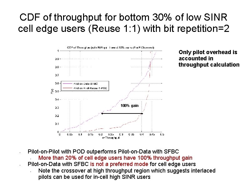
CDF of throughput for bottom 30% of low SINR cell edge users (Reuse 1: 1) with bit repetition=2 Only pilot overhead is accounted in throughput calculation 100% gain • • Pilot-on-Pilot with POD outperforms Pilot-on-Data with SFBC • More than 20% of cell edge users have 100% throughput gain Pilot-on-Data with SFBC is not a preferred mode for cell edge users • Note the crossover at high throughput region which suggests interlaced pilots can be used for in-cell high SINR users
Conclusions At cell edge, rank-1 precoding (POD) outperforms SFBC with interference suppression receivers SFBC uses 6 -pilots/antenna, POD can use up to 16 -pilots Pilot-on-Data with SFBC has very poor cell edge performance Pilot-on-Pilot with POD outperforms Pilot-on-Data with SFBC POD with higher number of pilots is useful for better channel estimation and better MMSE interference suppression POD with 16 -pilots/RB supports orthogonal pilots, whereas SFBC with 6 -pilots/ant does not support orthogonal pilot allocation Hybrid modes allowing CL-rank 1 precoding and SFBC degrades MMSE interference suppression gain Hybrid modes allowing CL-rank 1 precoding and OL rank- precoding (POD) provide high MMSE interference suppression gain Rank-1 precoding works well with conjugate data repetition (CDR) Suggest “Rank-1 precoding” for cell edge users” Pilot-on-Pilot with POD and CDR for cell edge users Pilot-on-Data with SFBC/SFBC+rank-1 precoding for in cell high SINR users For cell edge users : POD+CDR+Pilot-on-Pilot+16 Pilots per RB + pilot sequences with good cross correlation